Originally Web posted 24 September 2000
Content last modified
Saturday, 9 January 2021
Testing for Ground Loop Problems
Goal: ensure that each device has zero or one (preferably one) path to earth ground.
Preliminaries
Disconnect interconnected systems (computers, VCR/TV, interconnected audio components) and test each component with a power cord separately. Keep some paper (or other preferred data recording format) handy for writing notes to keep on file somewhere.
You will need some form of continuity tester… there is no escaping this requirement. Any of the following are OK: DMM (Digital MultiMeter), VTVM (Vacuum Tube VoltMeter), VOM (VoltOhmMeter), battery in series with appropriate flashlight-type bulb. If you do not have any of these device, you may wish to read Sonic’s DMM recommendations.
Knowledge of how to properly use your particular continuity tester is essential. The original owner’s manual and actual practice are two excellent and complimentary ways to achieve this. A decidedly inferior, yet possibly still useful, option is reading the page on this site entitled Simple Interpretation of Continuity Tester Readings.
Proceed no further until you have a continuity tester, and know how to use it. Once you are clear on how your test device displays an open circuit (test probes not touching) and a short circuit (test probes touching), you are ready to proceed with the actual tests.
Testing for Ground Loops - A/V equipment
- Pick a unit. Let’s start with a VCR. Disconnect the unit completely from everything else - all A.C., audio, video, and any other cables.
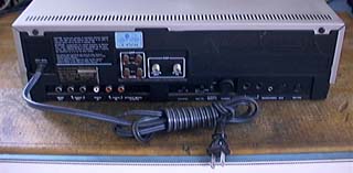
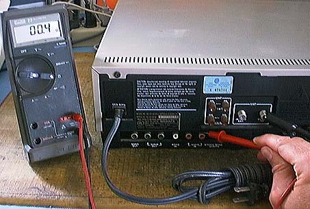
- Touch one probe of your test device (either probe) to the outer contact of the coaxial connector where the cable or TV antenna connects to the VCR. Keep this probe on this connection in the following steps until noted otherwise. (It’s fine to let go of this connection as you’re shuffling stuff around, just restore it as you do each of the following tests).
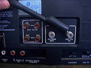
- Touch the other probe of your test device to the outer shell of the other similar-looking connector on the VCR. This should be the coaxial connector which connects to the TV (which you may or may not actually be using). Expect your tester to show a short circuit, or close to it. Record your results.

- If there are any other similar coaxial-style connectors on the particular device, test those as above, note their names (should be on the rear panel) and record their results. VCRs probably do not have any; fancy TVs may have several. Other stuff… who knows?
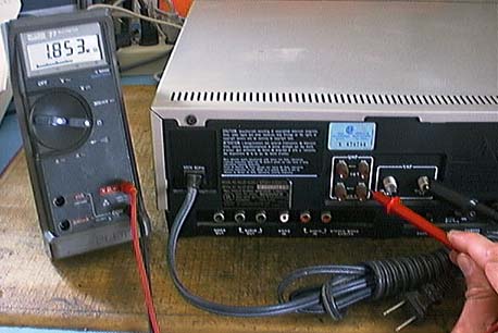
- Move the other probe to either of the prongs of the A.C. plug. Note the reading, and whether the prong is the wide one or the narrow one, or if they are both the same width. Repeat this step for the other prong on the A.C. plug. On equipment with three prongs, also repeat for the round grounding prong.
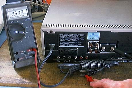
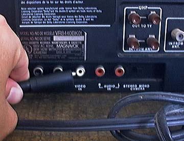
- Move the now-famous “other” probe to the outer shell of any of the RCA phono-style jacks, used for video and audio connections. Note and record the result.
- Quickly move the “other” probe to the remaining outer shells of the remaining RCA jacks. Expect the same results you just got. Only make notes if any of these respond differently - which one? what result?
- If there are any other styles of connectors to which you attach any sorts of wires or cables (other than speaker wires), perform similar tests on these other connectors. (In the case of standard home VCRs, there should almost never be any others).
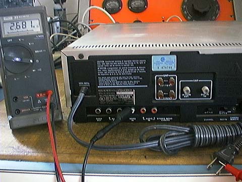
The above tests checked all normal paths from the cable (or roof antenna) coaxial connections to all other commonly-used interconnection points. Depending upon the specific equipment, there are probably other paths to check. In the case of the common home VCR and most home audio components, we need to check continuity between the A.C. plug contacts and the RCA jacks, since RCA-connector cables are commonly connected between equipment. Continuing:
- As in Step 2 above, touch one probe to the outer shell of one of the RCA jacks. Hopefully, you will have found that all RCA jack shells on the unit you are testing show a short circuit between themselves and the “F” connector of Step 2 above. If this is not true, make sure to use one of the RCA jack shells which did show a short circuit to the “F” connector of Step 2 above.
- Move the other probe to either of the prongs of the A.C. plug. Note the reading, and whether the prong is the wide one or the narrow one, or if they are both the same width. Repeat this step for the other prong on the A.C. plug. On equipment with three prongs, also repeat for the round grounding prong.
I cannot possibly exhaustively cover every possibility of ground loop paths for your particular equipment. The most common problem areas are any metallic connections (i.e. wire, not fiber optic) between separate components with A.C. cords, such as VCRs (and any other video devices that attach to a cable, satellite dish, or antenna) to TVs, and any audio components between themselves (i.e. CD player to receiver). The very most critical of these are connections shared between separate systems in separate rooms. In most homes, that would be limited to A.C. power and the cable TV cable. If you have very long standard home audio or A/V cables which interconnect systems in different rooms, those too are prime candidates for ground loops.
On the other hand, if you have a very complex whole-house entertainment system (usually installed by a professional installer), you are in a special category, and my instructions on this page are very likely to be insufficient. You will either need to become a ground loop expert yourself, or hire one, if you suspect ground loop problems.
In conclusion, since it is not possible for me to guess what other possible ground loop paths your particular setup might contain, i must leave it to you to set up additional tests, along the lines of those above, if you have other categories of copper wires which connect electronic systems in different rooms.
Testing for Ground Loops - computer equipment
Note: the author has less experience in this area than with A/V equipment. It would be wise to seek additional sources of information for corroboration. Most of the author’s test measurements were performed with Macintosh hardware; results for common IBM PC-compatible and/or other platforms’ hardware may vary.
By design, common home computer systems form small ground loops amongst their various components, i.e. the CPU to the monitor to the printer to the scanner, etc. As long as these systems are small enough to be fed off of one A.C. outlet/strip (or at least the same branch circuit), there should be no problems. As soon as these systems are networked to systems in other rooms, there is at least the possibility that there may be ground loops which may be detrimental to some equipment.
Home/small office computers are most commonly susceptible to ground loops via the following interconnections:
- Modems/Data Interfaces (via the powerline and the telephone line/cable)
- Wired Local Area Networks (via the powerline and the network cable)
- Analog Audio/Video connections (via the same paths as non-computer A/V equipment)
Analog Modems (56kbps and below)
The two external analog modems i’ve tested (33.6k and 14.4k) both have full isolation between the data cable shield and the telephone wires. Assuming that this is true for most modems, this is not likely to be a ground loop source. To make sure that your particular modem is not a ground loop source, measure for continuity between each of the modem’s telephone jack pins, and:
- The shield (outer shell) of the data cable connector for external modems
 , or
, or
- The CPU’s A.C. power ground pin for internal modems.
Cable “Modems”
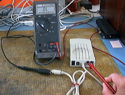
The one cable modem i have so far tested, a Motorola SB 5100, absolutely has the potential for serious ground loop creation. Whether or not this actually happens depends upon the data cable used between the modem and the destination (computer, broadband router, or other immediate “downstream” device). Both by visual inspection and an ohmmeter reading, we see that there is full continuity between the shields of all three data connectors on this device:
As discussed in the next section below, unshielded twisted pair (UTP) Ethernet cables, the most common, will prevent ground loops. If a shielded twisted pair (STP) cable connects the modem to the next device, a serious ground loop is entirely possible… even likely, if the dwelling also has the cable attached to a TV or other A/V equipment. The best cure would be to use a UTP Ethernet cable, if possible.
USB cables are shielded, and the shield path is complete to the connectors at each end (on the sample i tested), so using the USB connection on this cable modem will guarantee a ground loop. One would either need to switch to the Ethernet connection instead, or somehow insulate the shield or otherwise interrupt shield continuity at one end of the USB cable.
Other Broadband Internet Interfaces
DSL interfaces, ISDN interfaces, and other broadband equipment are all potential trouble sources. Having never personally used any of these, i can offer no specific advice. The same principles of measuring continuity between the grounding connectors (almost always the outer shell) on the computer side and the network side apply. Ideally, there should be no continuity. If there is, some way must be found to break the loop. The same “fix” which works for TVs and VCRs probably works just as well for cable modems, and will be covered on the next page. You will need to consult other resources to cure any ground loop problems with other wired broadband technologies.
Wired Local Area Networks
Probably the easiest test procedure is as follows:
- Disconnect everything from the CPU, except any external network adapters (such as AAUI to 10base-T, or serial port to LocalTalk).
- Connect one test probe to the CPU’s A.C. power ground pin.
- Touch the other test probe to each of the contacts of the network wiring connector.
As always, there should be no continuity. If there is, ground loop breaking procedures beyond which i am able/willing to document now may be necessary.
My Ethernet findings are mixed. Good isolation on the built-in 10base-T RJ-45 jack on my Power Mac 8600/300. Good isolation on an external AAUI-to-10base-2 (coaxial cable) Ethernet adapter. No isolation at the RJ-45 jack on an Asanté internal IIsi Ethernet adapter card set.
Luckily, the cabling used has everything to do with whether or not a ground loop is formed, and it appears that the most popular form of Ethernet cabling eliminates ground loops! If you are using standard unshielded twisted pair (UTP) Ethernet cables, there is no ground loop problem, since (in my limited testing) it appears that the 8 signal wires are isolated from chassis ground (do verify this on your system if problems persist and more obvious loops have all been eliminated).
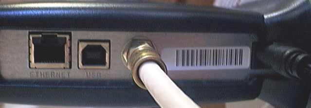
How do you know if you have UTP? Look at the connector:
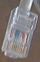
If it is the normal plastic connector shown above, you’re fine. If your connectors look like this yet are wrapped in metal, you have STP: shielded twisted pair. If your Ethernet cable connectors do not look like this at all, you’re probably connected via coaxial cable, and you almost absolutely have a ground loop problem. If you do have shielded twisted pair, and you happen to know that you cannot use regular UTP at your location, you will somehow need to interrupt the shield at one end. As with USB cables (discussed above in the Cable Modems section), one can insulate or otherwise disable the shield of one connector. If you have tools for installing RJ-45 connectors on your own cable, it is probably easier to make a custom cable by cutting the shielded connector off one end and installing a standard unshielded connector… at least for 100 Mbps and below speeds. The remaining original shielded connector will insure that the cable itself remains shielded.
If anyone besides me is still using PhoneNet-style LocalTalk connectors, it appears that most of those are well isolated and should present no ground loop problems. It would be worth checking yours, esp. if you have the actual Apple LocalTalk interface devices.
Analog Audio/Video connections
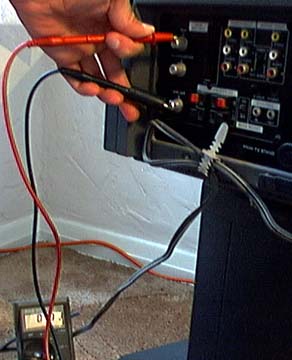
With the growing popularity of analog audio and/or video and/or RF (TV and FM tuners) connections on home computers, new avenues of computer ground loop agony have arisen. Any of the aforementioned connections which are actually used, and connect to anything extending beyond the immediate computer area (such as the T.V. cable, or an A/V system in another room), will have to be tested.
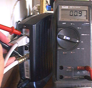
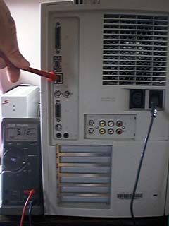
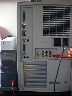
Treat the computer CPU as if it were a VCR, and follow the same testing procedures as above. Here is an example of measuring continuity between the shell of an audio RCA jack and the powerline ground pin:
Continue on to Curing Ground Loops
Begin at: What is a Ground Loop and why should I care?
 World O’ Electronics
 The Sonically Pure Pages
This Siber-Sonically Pure Page is  and
and  compliant.