Fluke 80i-1010 DC/AC Current Probe Notes
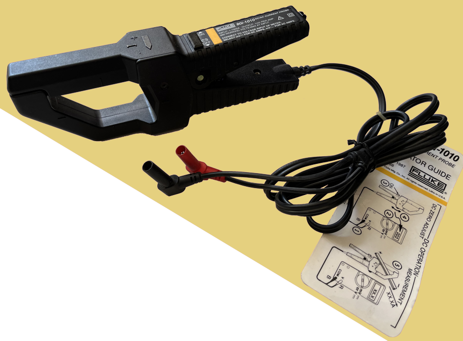
It amazed me how little information was online in October 2025 related to the Fluke 80i-1010 DC/AC current probe, or as i casually like to call it, amp clamp. All i found was a pair of lengthy not-really-edited videos:
Gratitude to YouTube video poster pa4tim for making the effort to record and upload those videos (though i do wish they’d been edited down to one continuous, clean video + audio). They were very useful for disassembly information.
Revisiting the situation in early October 2026, a clue-by-four reminded me that, duh, Fluke provided operating instructions which include a schematic diagram, calibration information, functional verification, and a parts list, in addition to the expected operating instructions, specifications, and warranty information. Unfortunately this document does not seem to be available from the Fluke website, but…
The instruction sheet is very, very useful—i recommend it to everyone who doesn’t already have a copy. It does not, however, discuss disassembly nor repair. On that basis, i present here and now more concise (relative to the videos linked above), text-and-still pictures information on this device.
My particular current clamp exhibited highly inconsistent readings, which massively varied when the clamp was firmly tapped, or the jaws opened then closed. This made measuring current draw on a moving vehicle impossible. Assuming contacts needed cleaning, i set about figuring out how to disassemble the clamp.
Disassembly
The videos from pa4tim proved informative. Here’s my more concise, text-based version, with a few pictures.
- Remove the batteries (if you haven’t already)
- Remove the plastic disc hinge pin covers
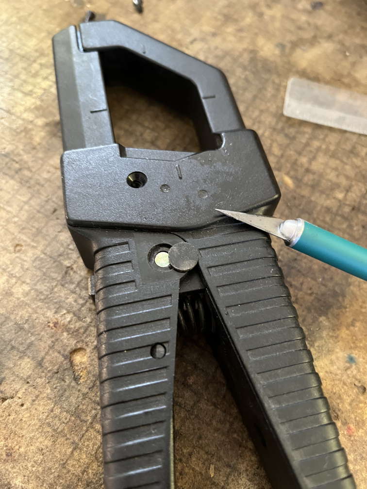
I used the tip of an x-acto knife to carefully pry each of them up and off. Held by adhesive. In this photo i’d already removed side screws because i did not know what i was doing. OK if you do that now, but i cover that further below, at a more appropriate point.
- Push out the pivot pin
Here’s the tricky part: pushing out the pin, not tapping or hitting! The video demonstrated a homemade sorta-puller arrangement. Here’s my version:
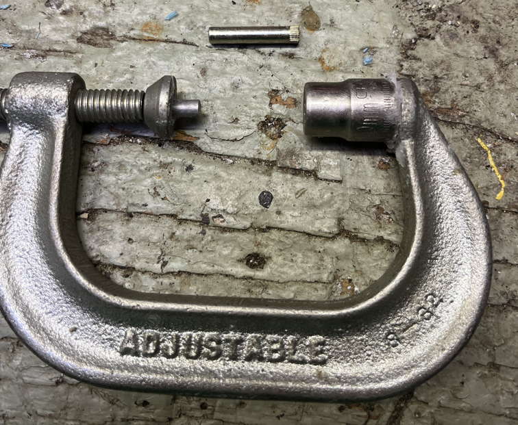
C-clamp of appropriate size, with a metal standoff similar to the pin diameter (slightly smaller) on one side, and a suitable socket (i used 10 mm 3/8" drive) on the other side. These items are held to the clamp by museum wax for ease and convenience.
Note that the current clamp hinge pin has one smooth end and one knurled end. It should be possible to see which is which via careful visual inspection prior to disassembly. We want to push on the smooth end with the metal standoff and let the socket receive the knurled end as it emerges from the clamp body.
Because the current clamp will want to spring apart once the pin is out, consider having another larger c-clamp gently hold the two halves of the amp clamp body together in their normal assembled resting state. I held this c-clamp firm and steady in a bench vise:
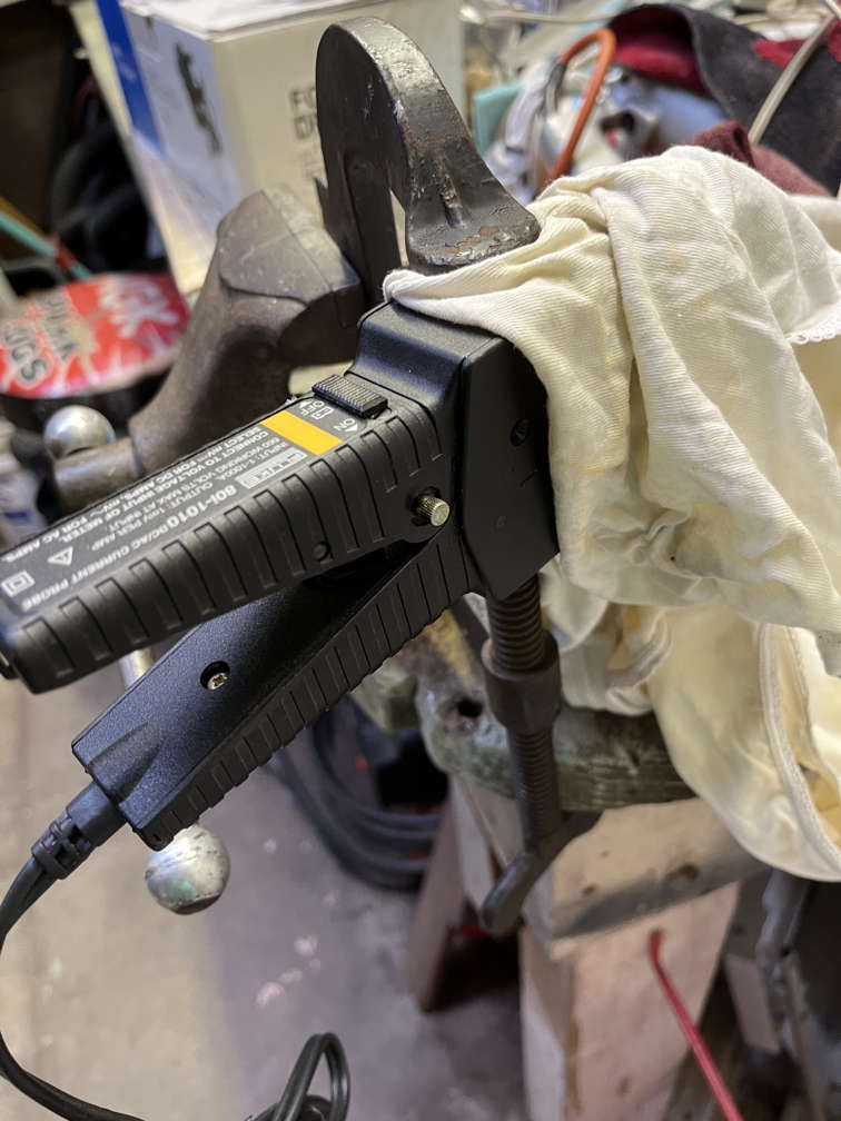
- Carefully remove the current clamp from the c-clamp, holding the current clamp together with your hand. Slowly release tension then remove the coil spring. The two halves of the current clamp can now be separated.
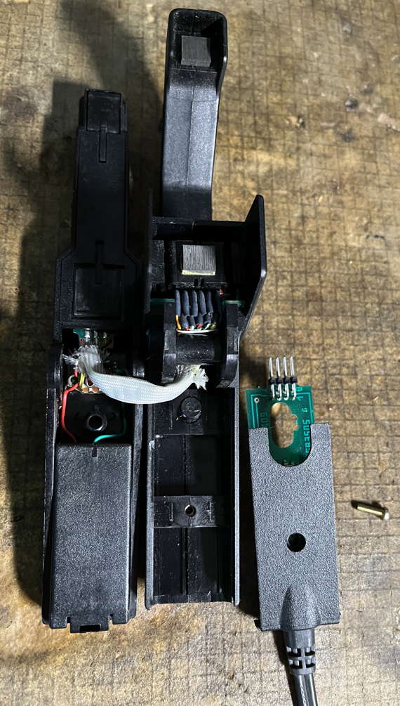
- Remove cable and its PCB (the main PCB)
- Unscrew the single screw on the interior of the clamp arm opposite the battery compartment
- Pull the assembly with cable in the direction of the cable (away from the main body of the current clamp) about 8 mm to unplug this board from an inner PCB. Watch the large plastic stop pin for guidance.
- Carefully lift and guide the cable PCB assembly out of the main current clamp body
- Remove inner PCB + laminations plastic retainer
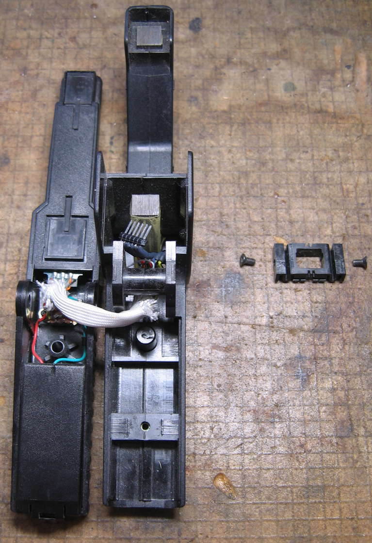
This is where the two side screws get removed. Once removed, the retainer lifts out:
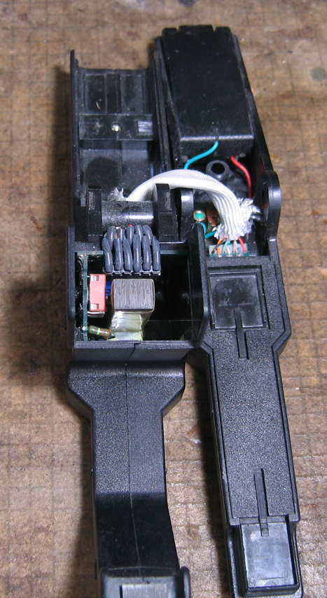
- Unplug the 6-pin visible connector at the top of the internal PCB assembly (“top” when the clamp is oriented as shown in the photo. I cannot imagine working on it in any other orientation).
Before it is unplugged, it looks like this:
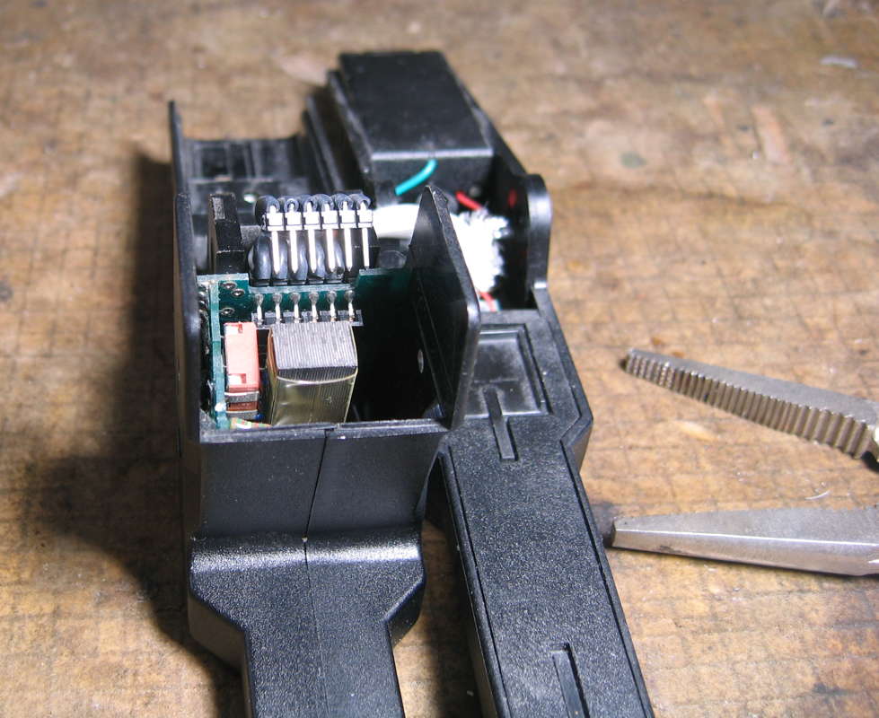
I used somewhat thin wide pliers (pointy Vise-Grips®) to grip the opposing short sides of the connector. In the video, pa4tim pried carefully at the seam between plug and socket. Either method works.
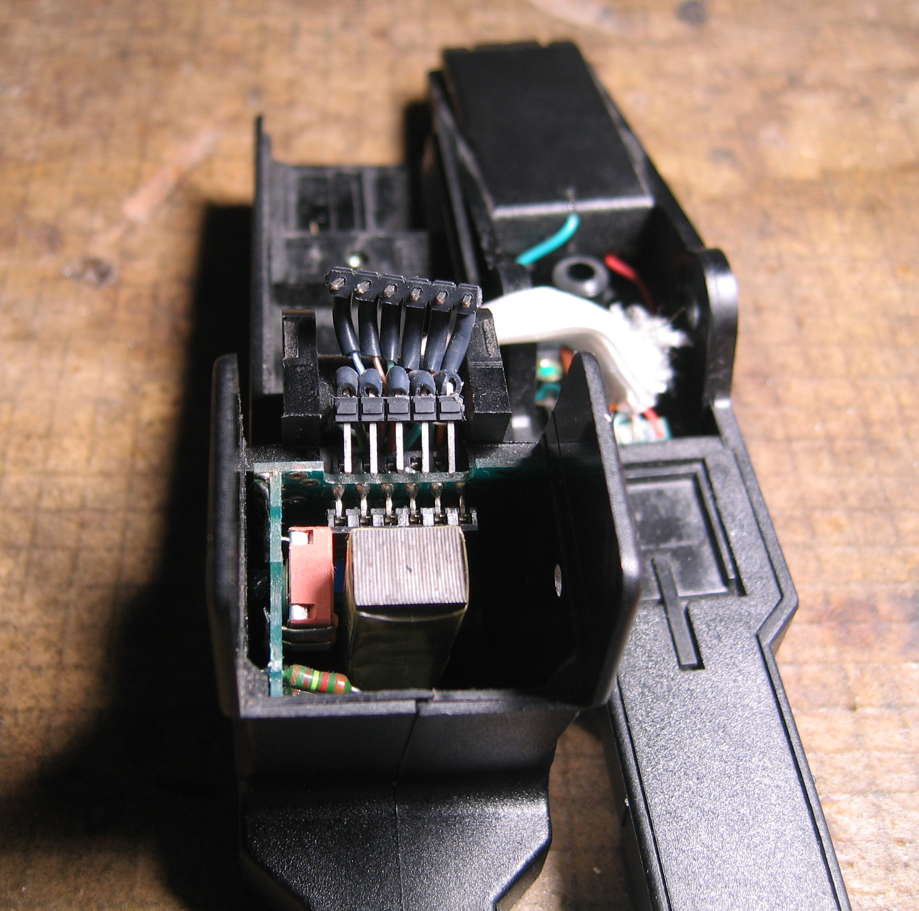
- We can now see yet another connector on the other (outer) side of the PCB, previously hidden. This too like the last one is a PCB header-style connector, this one with 5 pins. With even lower side clearance, i needed to use hemostats to unplug this one. Once unplugged, looks like this:
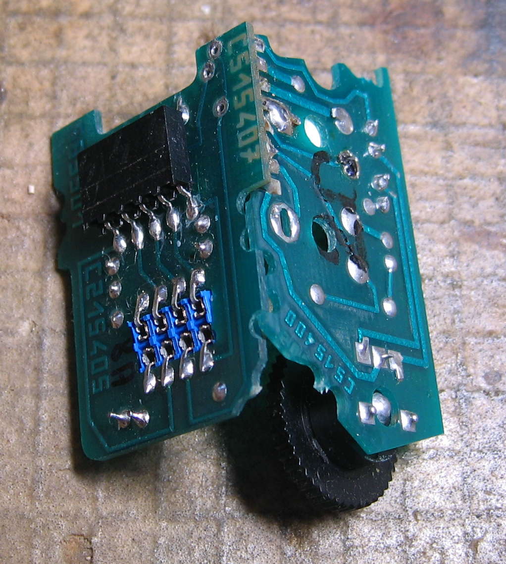
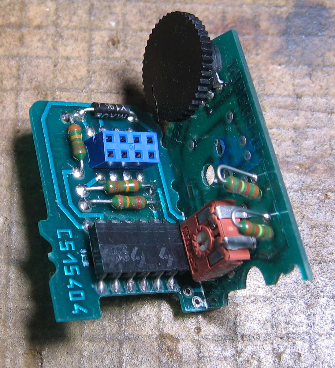
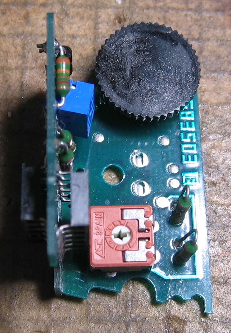
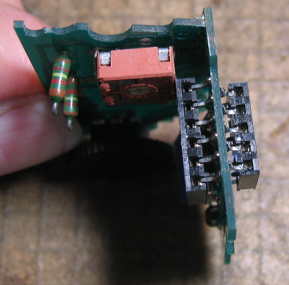
- Lift the circuit board assembly out. We see it is composed of two boards attached at a right angle:
Schematic and Circuit Notes
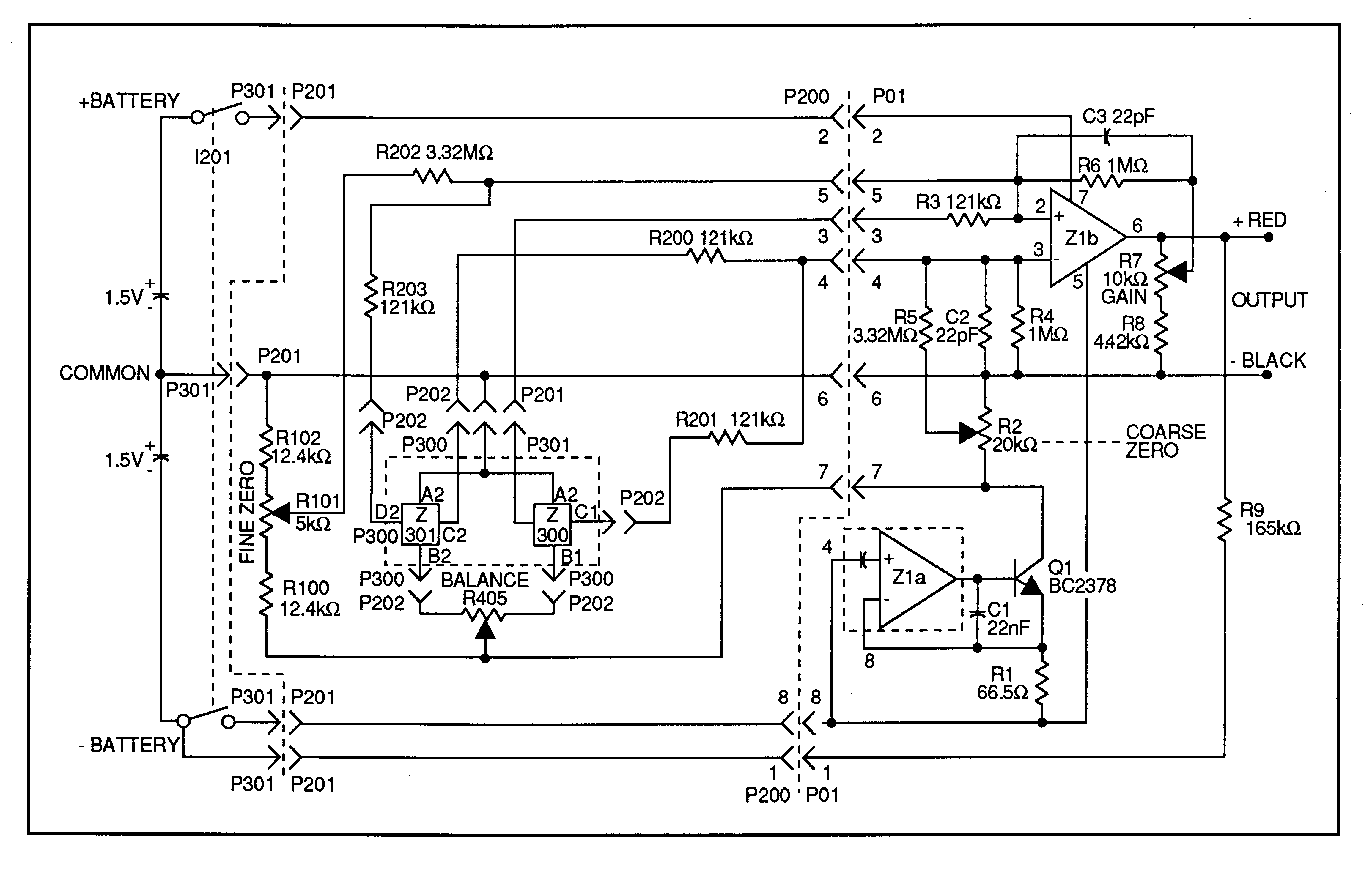
Before i bought a clue and remembered that i had the original instruction sheet (manual) with schematic, i blew away several days of life drawing my own from scratch. It’s very colorful, but much harder to follow than Fluke’s original. Hence mine is not here, and Fluke’s is, scanned from my original instruction sheet (Rev. 1 6/93):
Schematic Comments
Errata
There appear to be at least a couple of errors in the Fluke schematic—maybe the one upside of the days i lost drawing out my own:
- Q1 is supposed to be BC237B, not BC2378—we know this from the Replaceable Parts list of the Instruction Sheet, and some of us further know from typical BC transistor numbering. Further confusing things: my actual clamp uses BC547B.
- IC pinout. The data sheet i have for the LM10CLN shows pin 4 as V–, not pin 5. The sheet lists pin 5 as Balance, and it appears to not be connected on my clamp (but there could be a trace under the IC which i missed). The data sheet shows the reference section which Fluke lists as Z1a as having its + reference entirely internal, with no external connection to it. The output of Z1a is pin 1, which appears to have been omitted from the Fluke schematic.
- Not sure why Fluke has drawn Z1a in a dotted outline. It’s in the same package on the same board (main/output) as Z1b.
Schematic vs. Board Locations
The circuit itself is fairly simple. Trying to follow it across three PCBs and several connectors is less so.
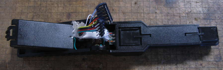
- The left of Fluke’s schematic up to the P301 junctions plus the dotted area around the Hall sensor corresponds to the Hall-effect PCB and associated wiring and connectors attached to the clamp arm with the battery compartment:
- The middle area of the schematic with the P2xx connectors mostly corresponds to the PCB of the two-board pair with the three connectors on it:
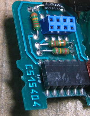
- Fluke’s schematic does not differentiate between each PCB which makes up the two-board pair. Hence the PCB with the zero adjust and Hall balance trimpots on it is included in that same middle area of the schematic:
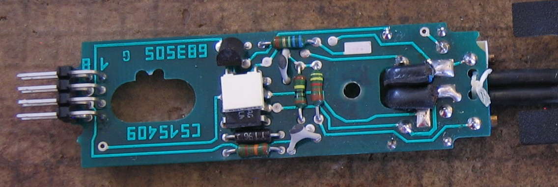
- The right of the schematic, right of the dotted line at the P200/P01 junction, is the main circuitry/output cable board:
Diagnostic Notes
Jumpy/Inconsistent Readings and/or Intermittent Operation
Odds are outstanding that the vast, vast majority of possible problems with this clamp-on current probe will be caused by one or more poor electrical connections. Between my personal experience and what pa4tim shared in his YouTube videos based on having repaired several Fluke 80i-1010 current probes (and other makes and models), most commonly look for:
- Damaged battery terminals: broken, corroded, bent, etc.
- Broken wires
- Dirty contacts in the power switch, connectors, and/or trimmer potentiometers
- Fractured solder joints
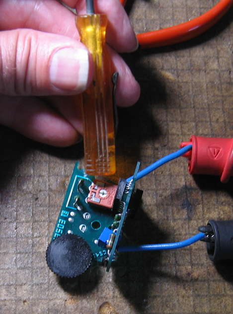
If going to the trouble of taking one of these current clamps apart, it makes sense to test as much as possible. I tested continuity of every wire and contact between convenient measuring points. For the trimmers, i did not want to mess up any adjustments, hence i left them alone, connected my ohmmeter, and tapped on them to detect intermittents:
Repair Notes
Repairing Jumpy/Inconsistent Readings and/or Intermittent Operation
Battery Contact Repair
My specific 80i-1010 current probe did/does have a broken battery contact. Take a look at this closeup of the opened battery compartment:
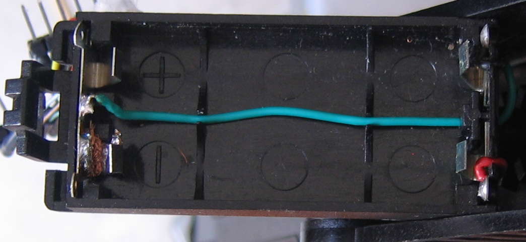
We see the circuit common green wire connected to the dual spring metal contact on the left. Top right is the negative contact for the V– supply, with its black wire barely visibile in the photo. Bottom right we can easily see the red wire for the V+ supply. Both these wires lead to the power switch (and the green connects to a terminal lug on the switch frame).
Notice shenanigans in the lower left corner. I’ve been careful to remove the AAA batteries from my 80i-1010 when it is not in use, so fortunately mine has zero corrosion issues. Unfortunately the wear and tear and (in my opinion) suboptimal shape and construction of the battery contacts led to this contact breaking. Since new, i’ve found it difficult to insert and remove the two AAA cells. Looking carefully you may be able to see my prior repair attempt: soldering the piece back on using solder wick copper mesh. In terms of electrical conductivity, this has worked well. In terms of restoring proper contact pressure, it’s a non-starter.
Up until this point, i’ve stuffed various things between the battery part and the back part of that contact, to try and re-establish contact pressure. I remember using the end of a cotton swab, but i don’t recall what else. Nothing was held in; everything fell out/got lost. None of them seemed to fit particularly well. It’s time for a different approach:
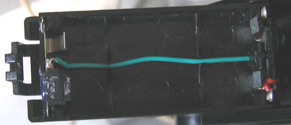
Foam and hot-melt glue!
I selected a piece of stiff foam from my vast scrap materials collection which required about the same force to depress as one of the undamaged spring metal battery contacts. Measured, trimmed, shaped to fit behind the broken contact and hold it in approximately the correct position.
To keep it from going AWOL like its predecessors, i applied hot-melt glue between the foam and back of the spring metal. Let it fully cool/cure, then applied a touch between the back side of the front (loose) contact and the front of the foam, to help positionally stabilize the contact beyond what the solder wick was already doing.
Connected the D.C. voltmeter across V– to V+ at the 5-pin connector. Inserted two decent AAA batteries into the battery compartment. Turned on the clamp’s power switch, and jostled that clamp arm assembly with vigor in various ways: nice and solid full voltage—no jumping around. Repeated for just V+ and just V– to circuit common: same result. So far, seems like a better fix. Hopefully long-term usage will be the same.
Power Switch Contact Cleaning
Going through the poor connection checklist above, there were no other issues with the battery contacts. There was no corrosion. There were no broken wires. There were no clearly fractured solder joints, though i did touch up a couple that might have been heading that direction.
The trimpots were all nice and stable: none jumped in resistance value at all with tapping. I did not explicitly test connector contact resistance, instead choosing to clean all of them with DeoxIT.
I did, however, find that the V– side of the power switch was very jumpy/flaky in terms of resistance. Operating the switch energetically multiple times On/Off/On/Off/On/Off did not change this. Spraying in DeoxIT D5 spray, operating the switch a couple of times, letting it soak/cure/process the recommended two minutes, then repeating the process with DeoxIT Gold G5 spray restored nice, stable low resistance (as for the V+ side all along) without having to remove nor open up the switch. This very likely was as much of an instability contributor as the funky battery contact.
Zero Adjust Knob Removal/Replacement
I had not intended to remove this knob. At one point during testing, i noticed that it kept turning in a full circle and beyond. Looking carefully, i’d knocked the knob loose on the shaft. The limit stops are part of the knob, related to a tab hanging off of it. The knob snaps off. First, i adjusted the trimpot to around mid-setting, with long nose pliers and the ohmmeter. Then i studied the knob to determine the proper orientation, finally snapping it back on. The limit stops again work properly, and the resistance changes are smooth and once again over the correct range.
Calibration
Fluke provides detailed calibration instructions in their Instruction Sheet. Initially i thought that no calibration would be needed, until my current clamp failed verification.
Trimmer Access and Locations
It is worth noting that all three trimpots are accessible from outside the clamp when it is fully assembled. Looks like Fluke used black (for the two on the back) and gray (for the one actually present and one unstuffed on the side) silicone to plug the calibration holes. Here are notated pictures:
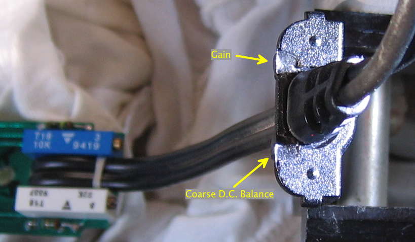
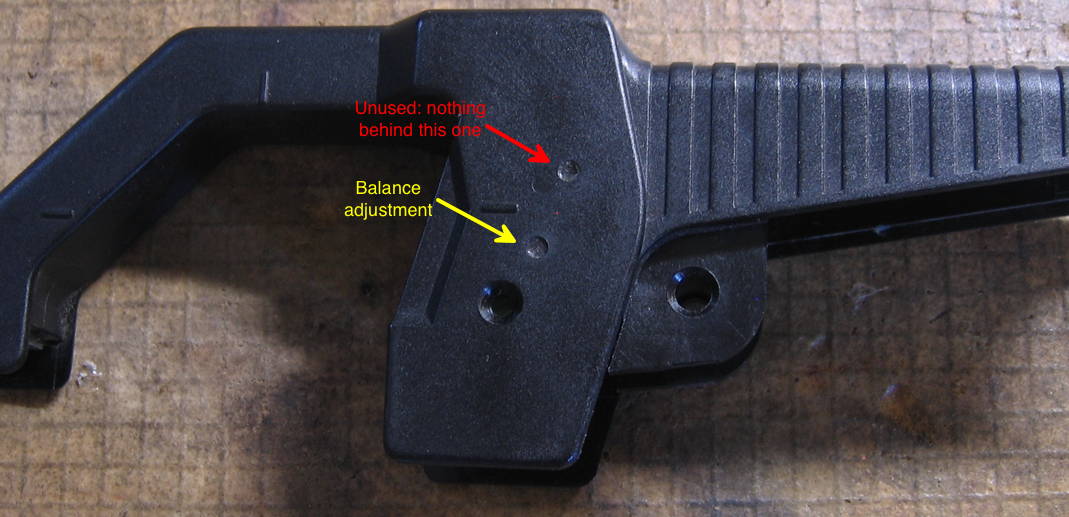
Use a small slotted screwdriver on any/all of these trimmers. I used the infamous Xcelite R3322 “Greenie”, which fit, whereas my usual yellow-handled small flat blade screwdriver was too wide to fit the openings.
Calibration Loop
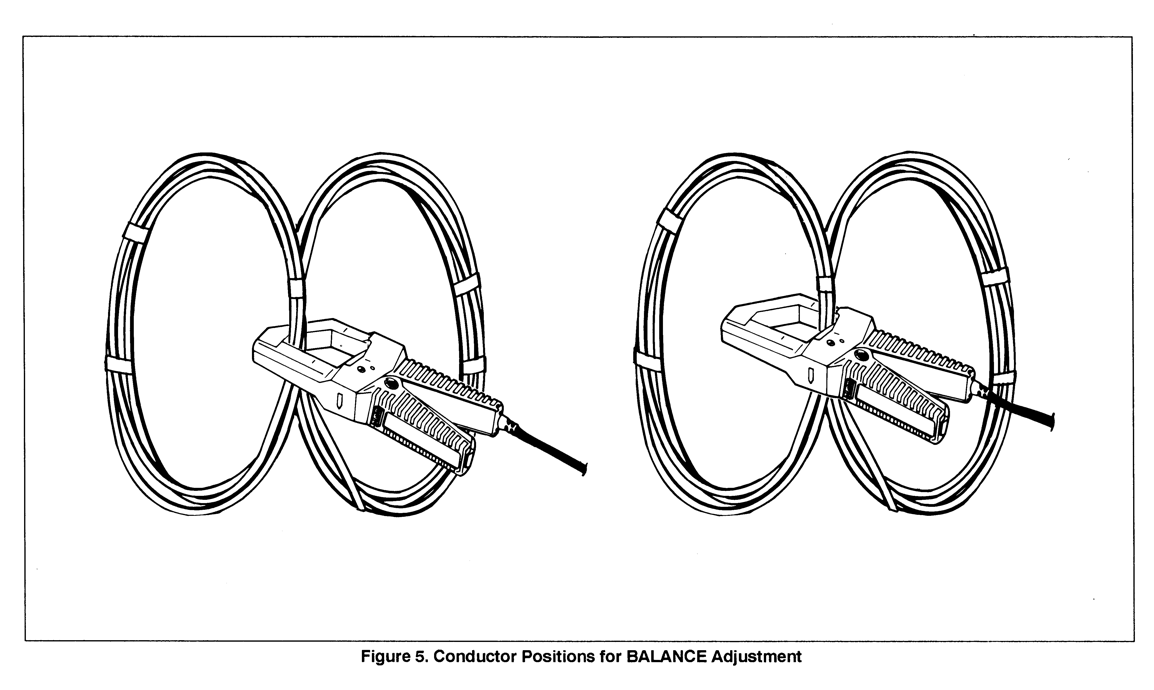
Besides the schematic, the other thing that’s a little annoying to view in the scanned online Instruction Sheet is Figure 5, Conductor Positions for BALANCE Adjustment, the illustration of the 10 turn (2 x 5 turns) coil(s) being used for this adjustment. Here’s my hopefully more viewable scan:
My Calibration Setup
I did/do not have all the equipment Fluke recommends for calibration: no DC/AC Voltage Calibrator, no Transconductance Amplifier. Instead, i arranged for D.C. and A.C. dummy loads, verifying the current through them and the coil loop with my Fluke 77 multimeter, whilst measuring the output of the 80i-1010 with my Fluke 87V multimeter. I realize this is bad metrology: the 77 has not been calibrated since it left the factory, circa 1983-84. Errors may (will) compound. Nevertheless, performance verification showed that my current clamp was far enough off that even with these added errors, i could still adjust it closer to correct than it was. Here’s a picture of my calibration test setup:
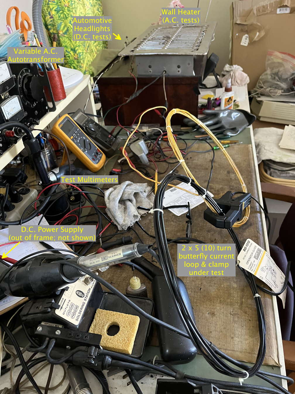
I realize this is a bad, over-cluttered photo, which is why it is annotated. Also, i took the photo as an afterthought once i was done, so i’d already disconnected the leads from the two Fluke DMMs.
I made a 10 turn (2 x 5 turn) coil loop as per Fluke’s instructions. For A.C. calibration/verification, i used an old bathroom wall heater, powered from wall power, regulated to exactly 5.00 A by a variable autotransformer, measured by the Fluke 77 in series in 10A A.C. mode. For D.C. verification (D.C. is not used for calibration), i used a parallel pair of 55W automotive headlights driven by an adjustable D.C. bench power supply, adjusted so the Fluke 77 showed exactly 5.00 A on its 10A D.C. setting.
Preliminary Coarse Zero Adjustment
As the name suggests, this is only a preliminary adjustment, since the adjustments interact. Nevertheless, i wanted to get the Fine Zero Adjustment thumbwheel (the one the user typically adjusts in normal usage) as close to exactly centered as possible. I counted knurls (lines on the thumbwheel knob) passing the pointer arrow on the clamp’s body. Mine has 26 total, so i counted 13 from one end to get it as close to mechanically centered as possible.
As you’ll read in section 6 of Fluke’s calibration instructions, the eventual final Coarse Zero adjustment is set for equal voltage offset at each end of the Fine Zero Adjustment trimmer’s mechanical range, obviating the need to be precise about mechanical centering.
Post-Repair Testing/Performance Verification
Specific to Your Repair
Obviously this will vary greatly. As an example: because i did a battery holder repair, i needed to test to ensure that the repair was holding the battery steadily enough to avoid intermittent problems, which i already described.
General Functional Testing
pa4tim made another good point in his video(s): it is entirely possible to connect everything up with the boards out of the clamp body, insert batteries, check that the battery level indication is OK (the 165 kΩ resistor to V– before the power switch), switch the power on, and attempt to zero the current probe on the DC range of a multimeter. I did this, and thankfully it worked just fine. Good very basic functionality assurance test before reassembling everything.
Performance Verification
Once again, the original Fluke Instruction Sheet is there for us: it contains detailed instructions for verifying D.C. and A.C. performance. As with the calibration, i did not have all the resources Fluke recommends, so i modified the procedure to come as close as i could. My current probe initially failed the verification after repair, with both A.C. and D.C. current readings being equally too low. Performed the calibration, repeated the verification, and it passed.
Thanks to John Fluke Manufacturing Company Inc. (for the original current clamp and the very thorough information in the Instruction Sheet), Internet Archive and Manuals Plus (for keeping the scan of the Instruction Sheet online), and possibly something in this article, hopefully we’ll all be able to continue making circuit-interruption-free high current measurements with our 80i-1010 current probes.
))Sonic Purity((