Originally Web posted 8 July 1996
Content last modified
Saturday, 9 January 2021
In the last article, we explored the desirability of maintaining absolute polarity (a.k.a. absolute phase) of audio signals from acoustic source to acoustic reproduction, and the likelihood that such is not necessarily the case, especially where those pesky head telephones[1] are part of the process. While quite a bit of discussion ensued regarding lack of standardization and optimum points in a system to correct polarity, there was little mention of testing and verification of actual polarity at a given point in a given system, nor relevant test equipment. Let us now fill that void…
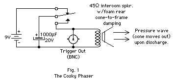
You may be disappointed to learn (as was i) that the human mouth (at least the author’s) is an inconsistent generator of pressure waves, especially when one does not wish to engage in destructive testing of ribbon mics and other sensitive, delicate, high-precision transducers. Enter the Cosky Phaser (described in the previous article, schematic shown in fig. 1)

Simplicity itself: the electrolytic cap. charges up to 9V. When the switch is thrown, the stored charge is dumped into the speaker, whose cone pushes outward, producing a pressure wave. Foam damping between the rear of the cone and the frame damps oscillations quite effectively, improving wave shape. The transducer under test is connected to a sufficiently sensitive noninverting oscilloscope input according to marked polarity standards, and some of the dumped charge triggers the ’scope via the BNC jack. Repeated throws of the switch (with a sufficient charging interval) produce easily visible, repeatable pulses of known polarity.
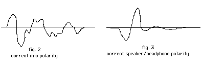
EIA-221-A-compliant microphones will produce a positive-going wavefront, usually with an oscillatory decay, exact shape dependent upon the microphone and its positioning with respect to the Cosky speaker (fig. 2). Tin-Can Standard speakers and headphone (RS-331) elements will produce a negative-going wavefront under identical conditions, typically with more oscillatory activity, with the first few cycles not infrequently exceeding the amplitude of the initial drop (or rise)(fig. 3).

As long as one is careful to focus in on the initial direction (positive-going or negative-going) of the first cycle of the pulse, the results are consistent and repeatable across a wide cross-section of transducers. The Cosky Phaser is cheap, simple, and easy to make, but interfacing directly to electronics is inelegant, and one’s hand does get awfully tired if there are a number of devices to measure…
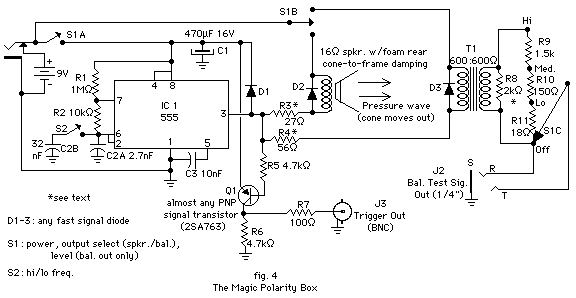
It didn’t take long to decide that the Age Of The IC dictated a more sophisticated approach, and that the versatile, omnipresent 555 timer would be the IC of choice. The working hypothesis: use a 1% duty cycle waveform, and find the most appropriate frequency to not only produce the fastest repetitions consistent with full mechanical oscillation decay, but also the most easily interpreted and visible ’scope waveform across the widest range of transducers and electronics possible. Extended experimentation yielded a circuit of only slightly greater complexity than the Cosky, but greatly improved functionality.

In addition to the built-in speaker of the original design, a transformer-isolated balanced output was added, level selectable for compatibility with mic, low line (-10 dBV to 0 dBu) and high line (+8 dBu) levels. The 600-600Ω transformer was the simplest path to ’scope/audio ground isolation, and balanced vs. unbalanced “brain-free” interfacing (slam it in, dial it up, and go!). 1/4" T-R-S was chosen for the output connector both for durability and “automatic” balanced/unbalanced “switching” via use of T-S (unbalanced) or T-R-S (balanced) plugs on the cable.
Best of all, the entire affair is sufficiently non-critical as to provide the perfect opportunity to use all those 20% carbon resistors, ungraded capacitors and the like you’ve been stockpiling all these years for just the proper occasion…. The only components i bought specifically for this project were the enclosure (on sale), and the battery clamp! A rotary switch was scrounged from a dead stereo receiver for the combination power/level/speaker/bal. out jack switch. Look for former function selector switches for ample contacts in a useful pattern, with the correct number of steps (5).
The PNP transistor inverts the negative-going (w.r.t. chassis) output of the 555 to a positive-going trigger pulse. Although there is no reason one couldn’t omit this stage, and merely trigger negative-going, i prefer to keep all outputs positive, both acoustic and electrical, for consistency’s sake. The series resistances were chosen empirically for best results (amplitude and waveshape) with the speaker and transformer at hand, so you may wish to vary these for yours. No doubt there’s a more elegant arrangement of flyback diodes, but i’m only making one of these, not thousands, and i had a lot of homeless funky diodes…. The 470µF supply filter should help extend the usefulness of weak/hi-Z batteries, though you can expect the trigger signal to "hang out" awhile after the unit is turned off.
Picking a 45-100Ω speaker may eliminate the need for the series R, but might as well use whatcha got. Plan on spending some focused time with a current-limited D.C. supply verifying the actual polarity of the speaker you plan to use: make certain the cone pushes out with the application of D.C., then mark the speaker terminal connected to the positive D.C. supply lead + or red (or whatever…) if it isn’t already. Make sure this terminal is the one going to the switched +9V rail, and all will be well. Tedious and obvious as this may seem, one doesn’t want to make an oversight here, lest one wishes an “opposite” polarity box! It’s also worth spending a few minutes experimenting with the best mechanical damping arrangement to get clean, non-ringy pulses out of the speaker (this may require iterations of microphone selection and damping experimentation).
The 2k transformer output load was empirically chosen for best rise time with minimal overshoot, unloaded into the ’scope—adjust as necessary. Putting the attenuator on the transformer output side yielded much more consistent waveshape at the different amplitude steps.
The 32nF C2b frequency-determining capacitance was originally the only C2. This odd value just happened to provide the best waveshapes for a wide variety of transducers with the 5 cm speaker used, around 40 Hz. There was never a problem interpreting results when a driver under test was connected directly to the Magic Polarity Box (or via a verified noninverting power amp, in the case of larger speakers), but measuring the waveshapes from some tweeters and midranges in multi-way speaker systems through the stock crossovers proved difficult. Hence, a frequency switch was added, along with C2a, as shown. 2.7nF yields about 414 Hz, the range of the highest frequencies which still had acceptable waveshape through the transformer. This has proven plenty high enough for any h.f. transducer + crossover to date, and might also prove useful for some extremely-limited-bandwidth electronics/media (though the author never experienced deficiencies through circuitry at 35-40 Hz). The parallel combination drops the low frequency to about 35 Hz, but no significant differences in waveshapes were found.
I highly recommend enlisting any cheesy, spare microphone (which doesn’t ring to the next county) for ease of testing speakers. Verify its polarity in the usual way, and attach a BNC (or whatnot) for direct ’scope attachment & guaranteed correct polarity every time (lest you left polarity inversion on… buta liba!). The little speaker in the Magic Polarity Box is more than enough for mics and headphone elements, and can be used with many speaker drivers, but isn’t likely to put out enough to kick large woofers, especially back through a passive crossover! Pump that line out into a power amp, verify electrical polarity with the ’scope as the signal enters the speaker, then use your reference cheesy mike to scope out each driver. Much faster!
Recorder/reproducers are straightforward electronic in/out affairs[2], but keep in mind the pulse will be delayed by whatever delay is inherent in the system, so it may lag substantially after the trigger pulse, and you may not see it right away if you just wrapped up amp or transducer tests. Be sure to trigger off your input channel and not the Box when looking at reproduced pulses after recording has ceased.
The Magic Polarity Box has sufficient output to directly drive a piece of wire acting as a flux loop for direct magnetic polarity testing pursuant to SMPTE RP 134-1994. Select high frequency & maximum output. Hold the wire parallel to the reproduce head gap(s), as close as possible, with the positive end of the wire at the bottom of the head as you face it (when confused, think Right-Hand Rule for clarification). ’Scope the deck’s output, and you’ve got your repro. results, plus a known reference for record->play tests.
Complaints? I cannot believe how little regard was given to polarity on some home audio equipment! Nakamichi 700 line in to line out: source inverts, tape mon. doesn’t. Same at headphone out. 700II: both tape and source invert at the line out, both noninverting at the h.p. out. This is one manufacturer and virtually the same machine! Similar results were obtained with other brands. My only other gripe is measuring polarity is now so much fun, i’m running out of things to measure!
[1] I never knew “headphones” was a contraction until reading an old FCC Element 3 Study Guide.
[2] if one is ignoring magnetic polarity, or assuming it is correct….
Polarity Matters (in case you missed it)