Section 5 — Electronic adjustments
(original pages 77−102)
Before making any electronic adjustments make certain that the mechanical adjustments discussed in Section 4 have been properly made.
The cartridge and the machine work together as a system and the overall machine performance is dependent on proper mechanical alignment.
For proper operation, the following adjustments must be made in the order outlined below.
NOTE: The mu-metal circuit board cover must be removed prior to making audio adjustments and reinstalled after adjustments are complete.
5.1 CARTSCAN Sensitivity
CARTSCAN sensors are factory adjusted to just illuminate the front panel indicator when the reflective foil is present. This inhibits false sensing from highly reflective cartridges without CARTSCAN labels. CARTSCAN adjustments are located on the CARTSCAN Printed Wiring Assembly mounted to the right cartridge guide (figure 10).
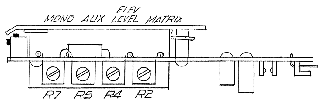
Figure 10
- All CARTSCAN inversion switches on the PLAY AMPLIFIER circuit board should be set to the off (left) position.
- Insert a cartridge with a MONO CARTSCAN label. Adjust the MONO sensitivity trimmer until the front panel MONO lamp illuminates. Then increase the sensitivity slightly.
- Remove and reinsert the cartridge several times. The MONO lamp should indicate reliably.
- Repeat with a MATRIX, ELEV LEVEL and AUX label.
5.2 Program Playback adjustments
All adjustments in this Section are located on the PLAY AMPLIFIER Printed Wiring Assembly (PWA). Play head azimuth, outlined in Section 4, must be correctly set before proceeding.
5.2.1 Playback Equalization
NOTE: No CARTSCAN lamps should be illuminated at this time.
- Connect a 600 ohm load to both the left and right playback amplifier outputs. Connect a high impedance voltmeter across the left channel load.
- While reproducing an NAB Standard Spot Frequency Alignment Tape (Fidelipac P/N 450-MONO, or 451-STEREO), note the level of the 1 kHz, −10 VU reference tone, as displayed on the external voltmeter.
- Adjust the low frequency (LF) and high frequency (HF) playback equalization trimmers for a reading equal to the reference tone at 50 Hz (LF) and 12.5 kHz (HF).
- For stereo machines, move the voltmeter to the right channel and repeat steps B and C.
5.2.2 Left Channel Normal Output Level
- Connect a 600 ohm load to both the left and right channel outputs. Connect a high impedance voltmeter across the left channel load.
- While reproducing a 1 kHz standard output level tape recorded at 160 nWb/m, set the LEFT NORMAL output trimmer for the desired level.
Machines are factory set to 0 dBm. If an output level less than −10 dBm is required, the reproducer output should be attenuated externally.
NOTE: There is a 6 dB level difference between balanced and unbalanced outputs. If an unbalanced voltmeter is used, set the output level 6 dB below the desired balanced output.
5.2.3 Left Channel Elevated Output Level
This adjustment is identical to Section 5.2.2 except:
- Use an ELEVATED LEVEL CARTSCAN label or the inverting switch on the PLAY AMP board to illuminate the ELEVATED LEVEL lamp.
- While reproducing a 1 kHz elevated output level tape recorded at 250 nWb/m, set the LEFT ELEV OUTPUT LEVEL trimmer for the desired level.
Machines are factory set to 0 dBm. If an output level less than −10 dBm is needed, the reproducer output should be attenuated externally.
If a 250 nWb/m output level tape is not available, use a 160 nWb/m tape and set the LEFT ELEV output level control for an output 4 dB below the standard level output.
NOTE: There is a 6 dB level difference between balanced and unbalanced outputs. If an unbalanced voltmeter is used, set the output level 6 dB below the desired balanced output.
5.2.4 Right Channel Level Balance
This is a factory adjustment and will not normally need resetting.
- Remove the PLAY AMP and mount it on the extender board.
- While reproducing a 1 kHz stereo reference tape, monitor U 10 pin 7 with a high impedance voltmeter or oscilloscope and adjust trimmer R100 for a null (minimum reading).
5.2.5 Right Channel Normal Output Level
This adjustment is identical to Section 5.2.2 except:
- Connect the external voltmeter across the right channel load.
- Adjust the RIGHT NORMAL output trimmer.
5.2.6 Right Channel Elevated Output Level
This adjustment is identical to Section 5.2.3 except:
- Connect the external voltmeter across the right channel load.
- Adjust the RIGHT ELEV LEVEL output trimmer.
5.3 Cue Detector Sensitivity
The sensitivity of the 150 Hz, 1 kHz and 8 kHz cue tone detectors may be individually adjusted. The adjustment trimmers are located on the TONE SENSOR PWA.
5.3.1 1 kHz Sensitivity
- Turn the 1 kHz trimmer fully counterclockwise.
- While reproducing a 1 kHz Cue Tone Test Tape recorded at −6 VU (80 nWb/m) (Fidelipac P/N 457), slowly rotate the 1 kHz trimmer so that the sensor just triggers and stops the machine.
NOTE: When adjusting the 1 kHz control wait 2 seconds after the cartridge starts. The sensor is disabled for this time.
5.3.2 150 Hz Sensitivity
- Turn the 150 Hz trimmer fully counterclockwise.
- While reproducing a 150 Hz Cue Tone Test Tape recorded at 0 VU (160 nWb/m) (Fidelipac P/N 457), slowly rotate the 150 Hz trimmer until the sensor just triggers and illuminates the front panel SECONDARY INDICATOR.
- Connect a high impedance voltmeter or oscilloscope to pin 41 of the remote control. Record the level of the 150 Hz “0” VU tone for later use.
5.3.3 8 kHz Sensitivity
- Turn the 8 kHz trimmer fully counterclockwise.
- While reproducing an 8 kHz Cue Tone Test Tape recorded at −10 VU (50.6 nWb/m) (Fidelipac P/N 457), slowly rotate the trimmer until the sensor just triggers and illuminates the front panel TERTIARY indicator.
5.4 Playback Meter Adjustments
- Set meter switch S2 on the TONE GENERATOR PWA to any position except RECORD.
- While reproducing a standard level 1 kHz test tape adjust the LEFT PLAY METER trimmer on the TONE GENERATOR PWA for a 0 VU indication on the left front panel meter.
- Repeat for the right channel by adjusting the RIGHT PLAY METER trimmer.
5.5 Program Record Normal Bias
The following adjustments: bias, record level, record equalization and record level balance are located on the RECORD AMPLIFIER PWA.
It is advantageous to set the machine for the automatic RECORD/PLAY mode under which the VU meters track either record input (when the RECORD button is pushed) or RECORD/PLAYBACK off the tape (when both RECORD and PLAYBACK are pushed). This setup permits the comparison of the input to the machine on the VU meters with the output on the external meter. It also helps to identify the 0 VU or −10 VU with dB readings on the external meter.
5.5.1 Left Channel Bias adjustments with External Oscillator
- Connect a 600 ohm load to both left and right reproducer outputs. Connect a high impedance voltmeter across the left channel load.
- Connect an audio oscillator to both left and right record inputs.
- Select an erased cartridge of at least 3.5 minutes duration. This cartridge should be in good working order and representative of cartridges presently used by your facility.
- Insert the cartridge and press the RECORD button. All CARTSCAN indicators should be off.
- Set the oscillator frequency to 10 kHz at −10 VU on the front panel VU meters.
- Start the machine and adjust the oscillator level for an indication on the external voltmeter that is 10 dB below the standard output level. See Section 5.2.2.
- Slowly rotate the LEFT NORMAL BIAS trimmer on the RECORD PWA from minimum (fully counterclockwise) to maximum (full clockwise) to find the maximum reading on the external meter. Set the LEFT NORMAL BIAS trimmer for a maximum reading on the external meter.
- Slowly rotate the LEFT NORMAL BlAS trimmer clockwise until the level indicated on the external voltmeter decreases by 1.5 dB (1.5 dB overbias).
5.5.2 Left Channel Bias adjustments with Internal Oscillator
- Connect a 600 ohm load to both left and right reproducer outputs. Connect a high impedance voltmeter across the left channel load.
- Set switch S4 on the TONE GENERATOR PWA to the −10 VU position.
- Select an erased cartridge of at least 3.5 minutes duration. This cartridge should be in good working order and representative of cartridges presently used by your facility.
- Insert the cartridge and press the RECORD button. All CARTSCAN indicators should be off.
- Set the test oscillator frequency switch on the TONE GENERATOR PWA to position 10.
- Start the machine and adjust the OSCILLATOR LEVEL trimmer for an indication on the external voltmeter that is 10 dB below the standard output level. See Section 5.2.2.
- Slowly rotate the left NORMAL BIAS TRIMMER on the RECORD PWA from minimum (fully counterclockwise) to maximum (full clockwise) to find the maximum reading on the external meter. Set the LEFT NORMAL BIAS trimmer for a maximum reading on the external meter.
- Slowly rotate the LEFT NORMAL BIAS trimmer clockwise until the level indicated on the external voltmeter decreases by 1.5 dB (1.5 dB overbias).
- Set S4 to the off position.
5.5.3 Right Channel with External Oscillator
Repeat steps in Section 5.5.1 except:
- Connect the external voltmeter across the right channel load.
- Adjust the RIGHT NORMAL BIAS trimmer on the RECORD PWA.
5.5.4 Right Channel with Internal Oscillator
Repeat steps in Section 5.5.2 except:
- Connect the external voltmeter across the right channel load.
- Adjust the RIGHT NORMAL BIAS trimmer on the RECORD PWA.
5.6 Program Record Elevated Level Bias
5.6.1 Left Channel Bias adjustments with External Oscillator
Repeat steps in Section 5.5.1 except:
- The ELEVATED LEVEL indicator should be illuminated. (Use a CARTSCAN label or the ELEVATED LEVEL inversion switch.)
- Adjust the LEFT ELEVATED BIAS trimmer.
5.6.2 Left Channel with Internal Oscillator
Repeat steps in Section 5.5.2 except:
- The ELEVATED LEVEL indicator should be illuminated. (Use a CARTSCAN label or the ELEVATED LEVEL inversion switch.)
- Adjust the LEFT ELEVATED BIAS trimmer.
5.6.3 Right Channel with External Oscillator
Repeat steps in Section 5.5.3 except:
- The ELEVATED LEVEL indicator should be illuminated. (Use a CARTSCAN label or the ELEVATED LEVEL inversion switch.)
- Adjust the RIGHT ELEVATED BIAS trimmer.
5.6.4 Right Channel with Internal Oscillator
Repeat steps in Section 5.5.4 except:
- The ELEVATED LEVEL indicator should be illuminated. (Use a CARTSCAN label or the ELEVATED LEVEL inversion switch.)
- Adjust the RIGHT ELEVATED BIAS trimmer.
NOTE: The recommended bias setting is 1.5 dB over bias at 10 kHz. It has been observed in practice that this bias setting is compatible with many tapes available. It is suggested, however, that reference be made to the tape manufacturer’s data sheet for specific bias recommendations. The CTR100 has sufficient bias current capacity to meet the requirements of all currently manufactured tapes, as well as those anticipated for the future.
5.7 Program Record Normal Level and Equalization
5.7.1 Left Channel Level with External Oscillator
- Connect a 600 ohm load to both left and right reproducer outputs. Connect a high impedance voltmeter across the left channel load.
- Connect an audio oscillator to both left and right record inputs.
- Select an erased cartridge of at least 3.5 minutes duration. This cartridge should be in good working order and representative of cartridges used presently by your facility.
- Insert the cartridge and press the RECORD button. All CARTSCAN lamps should be off.
- Set the oscillator frequency to 1 kHz and adjust the oscillator level for an indication of −10 VU on the front panel VU meter.
- Start the cartridge and adjust the RECORD potentiometer for an indication on the external voltmeter that is 10 dB below the standard reference level.
5.7.2 Program Record Normal Equalization, Left Channel, with External Oscillator
- Repeat steps A through F of 5.7.1 or continue if the level adjustment has just been completed.
- Change oscillator frequency to 12.5 kHz and adjust the left normal EQ trimmer on the record PWA for a 12.5 kHz level equal to the 1 kHz level as indicated on the external voltmeter.
- Set the oscillator to 50 Hz and slowly increase the frequency to 16 kHz. The level indicated on the external voltmeter should be equal to the 1 kHz level plus or minus 2 dB throughout the frequency range.
5.7.3 Left Channel Equalization Adjustment with Internal Oscillator
- Connect 600 ohm load to both left and right reproducer outputs. Connect a high impedance voltmeter across the left channel load.
- Set switch S4 on the TONE GENERATOR PWA to the −10 VU position.
- Select an erased cartridge of at least 3.5 minutes duration. This cartridge should be in good working order and representative of cartridges presently used by your facility.
- Insert the cartridge and press the RECORD button. All CARTSCAN lamps should be off.
- Set the test oscillator frequency switch on the TONE GENERATOR PWA to position 6.
- Start the cartridge and adjust the OSCILLATOR LEVEL trimmer for an indication on the external voltmeter that is 10 dB below the standard reference level.
- Set the test oscillator frequency switch to position 11 and adjust the LEFT NORMAL EQ trimmer on the RECORD PWA for a 12.5 kHz level equal to the 1 kHz level as indicated on the external voltmeter.
- Set the test oscillator frequency switch to position 1. The level indication on the external voltmeter should be equal to the 1 kHz level plus or minus 2 dB.
- Repeat step H with the oscillator frequency switch set to positions 2 through 12. The level indicated on the external voltmeter should be equal to the 1 kHz level plus or minus 2 dB throughout the frequency range.
- Set S4 to the OFF position.
5.7.4 Right Channel Adjustments with External Oscillator
Repeat steps in Section 5.7.1 and 5.7.2 except:
- Connect the external voltmeter across the right channel load.
- Adjust the RIGHT NORMAL EQ trimmer on the RECORO AMP PWA.
5.7.5 Right Channel Equalization adjustments with Internal Oscillator
Repeat steps in Section 5.7.3 except:
- Connect the external voltmeter across the right channel load.
- Adjust the RIGHT NORMAL EQ trimmer on the RECORO AMP PWA.
5.8 Program Record Elevated Level and Equalization
5.8.1 Left Channel with External Oscillator
Repeat steps in Section 5.7.1 except:
- The ELEVATED LEVEL indicator should be illuminated. (Use a CARTSCAN label or the ELEVATED LEVEL inversion switch.)
- Adjust the LEFT ELEVATED GAIN trimmer on the RECORD PWA.
5.8.2 Program Record Elevated Equalization
Repeat steps in Section 5.7.2 except:
- ELEVATED LEVEL should be illuminated. (Use a CARTSCAN label or the ELEVATED LEVEL inversion switch.)
- Adjust the LEFT ELEVATED EQ trimmer on the RECORD PWA.
5.8.3 Left Channel Equalization Adjustment with Internal Oscillator
Repeat steps in Section 5.7.3 except:
- ELEVATED LEVEL should be illuminated. (Use a CARTSCAN label or the ELEVATED LEVEL inversion switch.)
- Adjust the LEFT ELEVATED EQ trimmer on the RECORD PWA.
5.8.4 Right Channel adjustments with External Oscillator
Repeat steps in Section 5.7.4 except:
- ELEVATED LEVEL should be illuminated. (Use a CARTSCAN label or the ELEVATED LEVEL inversion switch.)
- Adjust the RIGHT ELEVATED EQ trimmer on the RECORD PWA.
5.8.5 Right Channel Equalization adjustments with Internal Oscillator
Repeat steps in Section 5.7.5 except:
- ELEVATED LEVEL should be illuminated. (Use a CARTSCAN label or the ELEVATED LEVEL inversion switch.)
- Adjust the RIGHT ELEVATED EQ trimmer on the RECORD PWA.
5.9 Right Channel Record Level Balance
This is a factory adjustment and will not normally need resetting.
- Remove the RECORD PWA and mount onto the extender board.
- Turn the cleaning switch on.
- Turn S4 on the TONE GENERATOR PWA to the “0” position.
- Set the test oscillator frequency switch on the TONE GENERATOR PWA to position 6.
- While monitoring U 12 pin 7 with an oscilloscope, adjust R95 for a null (minimum reading).
- Turn off the cleaning switch.
- Set S4 to the OFF position.
- Re-install the RECORD AMP PWA.
5.10 Internal Oscillator Level
- Connect a 600 ohm load to both left and right reproducer outputs.
- Connect a high impedance voltmeter across the left channel load.
- Select an erased cartridge of at least 3.5 minutes duration. This cartridge should be in good working order and representative of cartridges used by your facility.
- Insert the cartridge and press the RECORD button. All CARTSCAN indicators should be off.
- Turn S4 on the TONE GENERATOR PWA to the “0” position.
- Set the test oscillator frequency switch on the TONE GENERATOR to position 6.
- Start the cartridge and adjust the test oscillator level trimmer on the TONE GENERATOR PWA for an indication on the external voltmeter that is equal to the indication when reproducing standard reference tape in Section 5.2.2.
- Set S4 to the OFF position.
5.11 Record Elevated Level Gain Adjustment with Internal Oscillator
5.11.1 Left Channel
- Connect a 600 ohm load to both left and right reproducer outputs.
- Connect a high impedance voltmeter across the left channel load.
- Select an erased cartridge of at least 3.5 minutes duration. This cartridge should be in good working order and representative of cartridges used by your facility.
- Insert the cartridge and press the RECORD button. The ELEVATED LEVEL indicator should be illuminated. (Use a CARTSCAN label or the ELEVATED LEVEL inversion switch.)
- Turn S4 on the TONE GENERATOR PWA to the “0” position.
- Set the test oscillator frequency switch on the TONE GENERATOR PWA to position 6.
- Start the cartridge and adjust the LEFT ELEVATED GAIN trimmer on the RECORD AMP PWA for an indication on the external voltmeter that is equal to the indication when reproducing the elevated level reference tape in Section 5.2.3.
- Set switch S4 to the OFF position.
5.11.2 Right Channel
This adjustment is identical to Section 5.11.1 except:
- Connect the external voltmeter across the right channel load.
- Start the cartridge and adjust the RIGHT ELEVATED GAIN trimmer on the RECORD AMP PWA for an indication on the external voltmeter that is equal to the indication when reproducing the elevated level reference tape in Section 5.2.6.
5.12 Record Phase or Group Delay Compensation
Record phase compensation is a factory adjustment and will not normally need resetting.
- Remove the RECORD AMP PWA and mount it on the extender board.
- Connect a 600 ohm load across the left and right reproducer outputs.
- Connect the left channel output to the vertical input of an oscilloscope.
- Connect a 1 kHz square wave generator to the left and right record input.
- Select an erased cartridge of at least 3.5 minutes duration. This cartridge should be in good working order and representative of cartridges used by your facility.
- Insert an erased cartridge and press the RECORD button.
- Adjust the square wave generator level for a −10 VU indication on the front panel VU meters. All CARTSCAN indicators should be off.
- Start the cartridge and adjust R46 for maximum squareness and minimum overshoot as monitored on the oscilloscope.
- Connect the right channel output to the oscilloscope input and adjust R81 for maximum squareness and minimum overshoot.
5.13 Program Record Meter Calibration
5.13.1 Bias Meter Calibration
- Turn the cleaning switch on.
- Set S1 on the TONE GENERATOR PWA to the PROGRAM BIAS position.
- Press the RECORD button and start the machine.
- Adjust the LEFT RECORD BIAS trimmer on the TONE GENERATOR PWA for a 0 VU indication on the left front panel VU meter.
- Adjust the RIGHT RECORD BIAS trimmer for a 0 VU indication on the right front panel VU meter.
- Turn the cleaning switch off. Set S1 to the NORMAL mode.
5.13.2 Record Level Meter Calibration
- Turn the cleaning switch on.
- Set S1 on the TONE GENERATOR PWA to the NORMAL position.
- Set S2 on the TONE GENERATOR PWA to the RECORD position.
- Set S3 on the TONE GENERATOR PWA to INPUT/OUTPUT.
- Set S4 on the TONE GENERATOR PWA to the “0” position.
- Set the test oscillator frequency switch on the TONE GENERATOR PWA to position 6.
- Press the RECORD button, and adjust the LEFT and RIGHT RECORD INPUT LEVEL trimmers on the TONE GENERATOR PWA for a 0 VU reading on the front panel VU meter.
- Set S3 on the TONE GENERATOR PWA to TAPE/OUTPUT.
- Start the machine and adjust the LEFT and RIGHT REC TAPE trimmers on the TONE GENERATOR PWA for a 0 VU reading on the front panel VU meter.
- Turn the cleaning switch off. Set S1 and S4 to their CENTER positions.
- Set S2 and S3 to any desired position.
5.14 Cue Bias Adjustment
- Connect a high impedance voltmeter to remote control pin 41.
- Insert an erased cartridge into the machine.
- Start the cartridge, press and hold the TERTIARY record switch and adjust the CUE BIAS trimmer on the RECORD AMP PWA for a maximum signal as displayed on the voltmeter.
5.15 Cue Record Level
- Connect a high impedance voltmeter to remote control pin 41.
- Insert an erased cartridge into the machine.
- Start the cartridge, press and hold the SECONDARY button and adjust the CUE RECORD trimmer on the RECORD AMPLIFIER PWA for a level indication 6 dB greater than the level recorded in Section 5.3.2.
5.16 Cue Metering
- Set S1 on the TONE GENERATOR PWA to CUE/BIAS SIG.
- Insert an erased cartridge into the machine.
- Start the cartridge, press and hold the SECONDARY button and adjust the CUE BIAS trimmer on the TONE GENERATOR board for a 0 VU reading on the left front panel VU meter. Adjust the CUE OUT trimmer on the TONE GENERATOR PWA for 0 VU reading on the right front panel VU meter.
5.17 Test Oscillator Distortion Adjustment
This adjustment is factory set and will rarely, if ever, need correction.
- Remove the TONE GENERATOR PWA and install it on the extender PWA.
- Connect a distortion analyzer to U8 pin 6.
- Set the test oscillator frequency switch to position 6.
- Alternately adjust R49 and R50 for a minimum (less than 1%) distortion reading.