Originally written and posted 2 June 2001
Content last modified
Wednesday, 20 August 2025
External links last verified Wednesday, 20 August 2025
There has been a great deal written about X10 Wall Switch modules, including many modifications for meeting several objectives. It used to be possible to visit the Home Automation Knowledge Base Wall Switch Modification (Dead Link, remaining here for archive research purposes) page and ferret around there for all sorts of useful information compiled by fellow X10ers. Since the demise of Ido Bartana’s site, one now has to search around and hope.
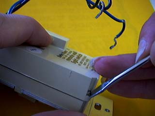
The original purpose of this page was and is to provide a pictorial description of WS module disassembly, to hopefully help make the process easier and less frustrating. In August 2025 some modification information which used to be on other sites was added, including what i believe to be a safer variation of the “3 wire” a.k.a. Add a Neutral modification.
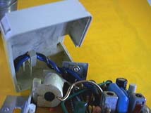
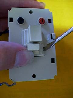
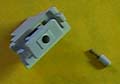
Keep track of the small roundish plastic plunger and the tiny spring behind it:
Basically the reverse of disassembly, with a few helpful tricks.
 IMPORTANT: This information is provided AS-IS, for informational purposes only, with no warranty whatsoever. Neither Sonic Purity nor anyone at Siber-Sonic.com can control your ability to successfully and safely utilize this information, and we accept no responsibility for anyone’s actions (beyond our own) related to the content of this website. X10 equipment utilizes the A.C. power line, which is dangerous. Do not attempt any of these modifications if you have any doubt about your ability to work safely with household powerline-operated devices. It is your responsibility to know and understand common safety procedures, especially those involving electricity at potentially dangerous power levels!
Reference schematic, courtesy of S. M. Bloom, modified by me:
Apologies for the funkiness of my edits: software complications. If anyone reading this is willing to give or affordably sell me a license to the Intaglio program version 3 (or later?) for Macintosh, please contact me. Being able to use that program on a quasi-modern Mac will help me make better drawings more easily.
This schematic might have originally been drawn for the old-style wall switch modules. I found at least one discrepancy between the original and my actual module: the 330kΩ zero cross detector (i think?) resistor connects to the triac side of the inductor in series with the blue lead (lamp) rather than the switch/lamp side. There may be other discrepancies. I lack the time to go through part-by-part to verify the schematic’s accuracy.
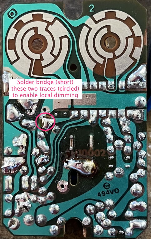
This is shown as triangle 1 on the schematic. Short across the parallel 0.47µF electrolytic capacitor and 470kΩ resistor. Some folks like to crush the capacitor or twist it to short its leads. Since i usually have the circuit board out for full contact cleaning anyway, i prefer the more elegant addition of a solder bridge:
Dimming is achieved by pressing and holding the on/off button. The light will cycle between full-on to full-dim, then back to full-on. Let go at the desired brightness level. Brief presses still execute standard local On and Off, as before.
Decades ago, readily-available X10-compatible wall switch modules were two-wire. In recent years (maybe the last decade or longer as of 2025), “3 wire” wall switches with the white grounded a.k.a. “neutral” wire already part of the switch have been readily available—no need to modify. One such example sold by x10.com as of August 2025 is the XPDI3 Dimmer 120 VAC 500W Inductive wall switch module.
The main reason to include this modification information is for folks like me with a collection of the older two-wire wall switch modules who find it more desirable to modify what we have rather than buying something new. Also, earlier presentations of this mod have not included adding any safety devices to take the place of removing the lamp being controlled from the module’s circuit power, which i consider potentially dangerous.
This modification is shown as triangle 2 on the schematic, in four places, all in the upper left.
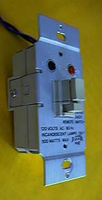
The standard one-way WS467 X10 wall switch module is a two-wire device. Wired in series with a light fixture, it derives power for its circuitry through the impedance of the lamp(s) in the fixture. Worked great for incandescent lamps; not so well for compact fluorescent lamps and even more so for LED lamps: the current required by the X10 circuitry is sufficient to turn an LED lamp on, somewhere between dim and full, often with pulsing or flickering as the lamp’s electronics struggle with what they sense as an electrically undefined state between full voltage On and no voltage Off.
Disconnecting the X10 module circuitry which draws power from the line leading to the blue wire (and hence the lamp) and instead connecting these points to the white grounded power connection (“neutral”) allows the X10 circuitry to be powered separately from the lamp. With no more current flowing through the lamp when Off, the module can now function correctly with many/most LED “bulbs”.
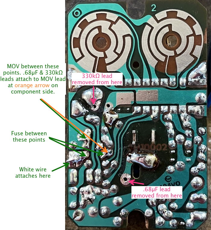
Notice that in addition to moving the .68µF signal detect + power supply connection and the 330kΩ zero cross detection (i think?) off the line leading to the blue Lamp lead over to the added white “neutral” wire, a series fuse and shunt metal oxide varistor (MOV) have been added. In the original two-wire arrangement, the lamp being controlled not only provided power for the X10 circuitry, but also circuit protection, being a significant series impedance. When connected to the grounded power conductor (“neutral”), this circuit protection is gone, hence we need to add it back.
Where did these component values come from? Other X10 modules, such as the LM465 Lamp Module, AM486 Appliance Module, etc. You’re welcome to substitute something else for the 62mA Littelfuse Pico II series 0251.062 fuse and/or the 11 Joule 7 MM diameter radial 130V Littelfuse V130LA2P MOV, as long as whatever you use provides equivalent circuit protection you, your insurance company, and any other relevant authorities deem acceptable.
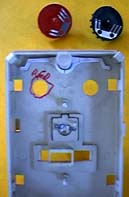
The P.C.B. has holes and traces which appear to be for the 3-way version, unstuffed in the 1-way version. If you’re doing the 3-way mod also, you’ll likely want to reserve those for those components (discussed below). If, like me, you’re working on a 1-way switch and have no need to modify it to be a 3-way, there are some useful places for mounting the small fuse and the MOV, as well as for attaching the added white wire. Here’s what my modified module looks like on the component side:
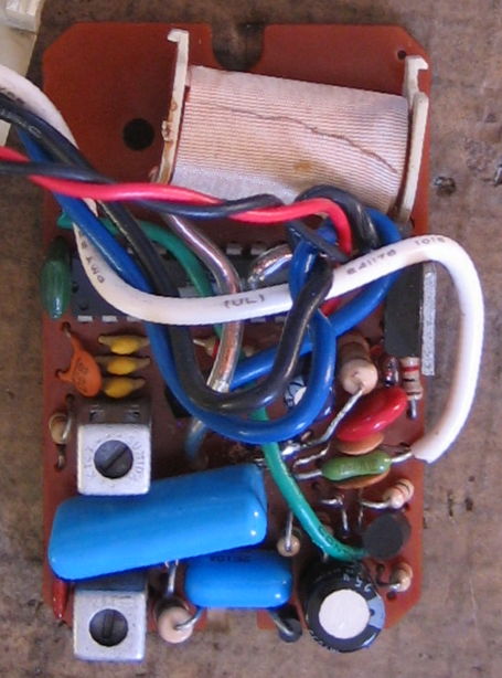
The added fuse (green body with axial leads), white wire, and MOV (red disc) utilize existing unstuffed PCB holes and traces. I tortuously twisted and bent the fuse end MOV lead on the component side of the board to get it to reach the removed ends of the larger blue .68µF mylar (guessing) capacitor and 330kΩ resistor (big, standing up just above red MOV in the photo), as there were no more suitable free board holes and this avoided needing to attach other wire segments to hook everything up. It’s not pretty and it might not survive shipping without bending and shorting something, but for my application it works.
The twisted red and black wires are another mod: paralleling the built-in front push switch with an external normally open pushbutton switch. They are unrelated to any of the mods described on this page or the schematic. I’m building this wall switch module into a specialized light fixture, where it’s not reasonable to mount it as the standard wall switch that it is.
Here is a view of the “neutral” mod on the foil side, notated:
Have a 1-way X10 wall switch you need to be a 3-way? No problem! This mod is shown as triangle 3 on the schematic. Add the two diodes, one resistor, and appropriate gauge and red-colored insulation wire as shown, and there you are. In case for some reason the schematic image is not loading, the 1N4148 diode parallels the internal front pushbutton switch, with its cathode connected to circuit common (same as the black Line wire). The connection NOT circuit common has a 10kΩ resistor in series, a 1N4004 diode in series with that resistor (cathode to resistor), and the added red wire connected in series at the 1N4004’s anode.
I have not done this particular modification, so no picture(s).
World O’ X10 ![]()
![]() The Sonically Pure Pages
The Sonically Pure Pages
This Siber-Sonically Pure Page is ![]() and
and ![]() Transitional compliant.
Transitional compliant.