Note: I am not calling out part numbers, e.g. C6 or R18 or Q1, because these not only vary from device to device, but also within production runs of the same device. I have found that X10 tends to use the same part in each position even when the call-out nomenclature changes. In other words, in controllers, the circuit which outputs the
PLC signal sometimes has a driver transistor. When it does, it is in my experience a 2SD667, whether it’s called Q1 or TR1 or something else entirely.
Assorted Failures of All Kinds: Electrolytic Capacitors
The design of X10 circuits demand a great deal from electrolytic capacitors, especially those in power supply circuits of X10 devices lacking a power transformer, which is the majority of them. Always visually inspect all electrolytic capacitors in X10 devices having issues, and replace any with visual signs of trouble. Those with access to sillyscopes (oscilloscopes) may consider checking waveforms across various electrolytic capacitors in malfunctioning X10 devices, to see whether the waveform is reasonable or not.
Power Surge Repair/Recovery
If you live in a lightning-prone area and/or your house wiring is suboptimal (esp. in terms of service grounding references), your X10 components will happily notify you of this/these fact(s) via blowing out. I give high credit to the X10 design engineers: the built-in MOV-based surge protection does amazingly well not only keeping the X10 devices from igniting, but often preserving the rest of the circuitry.
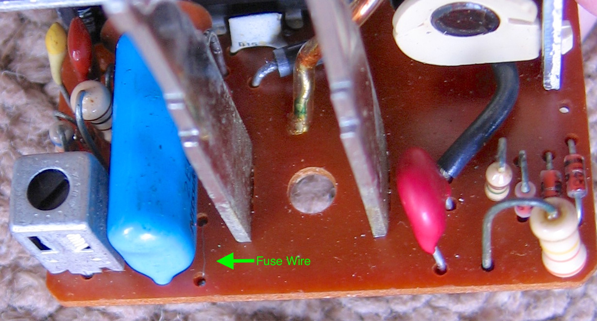
To achieve this, one or more MOVs per X10 device give up their lives, often in very visible, explosive manners. With the possible exception of some very early BSR brown era devices, all X10 devices i’ve seen have small bare wire fuses in series with at least the MOV (older designs) if not most of the circuitry (newer designs).
X10 MOVs
As noted several places, X10 (the company, whichever one/owner at a given time) loves to use the same parts across many different products, which totally makes sense. The original small MOV in my mother’s PR511 Motion Sensor was a VDR 07D221K. Via research done years ago that i have long forgotten, i concluded that a Littelfuse V130LA2P 130V 11 Joule 7 mm radial varistor from their LA series is entirely suitable for most X10 devices. As of July 2021, this part remains available from Digi-Key as their number F3002-ND.
X10 Fuses
How does one identify a part which has no package, hence no part number? Unless it shows up in documentation, one doesn’t. Figuring out X10 fuse values can be an exercise in frustration.
If anyone formerly with Pico Electronics Ltd. or any iteration of X10 truly knows what fuse (wire) values were used during manufacturing, i would love to receive correct, accurate information from you and present it on this page. Thanks!
Lacking actual X10 internal fusing information (which i for one have never seen), reverse engineering is our destiny. Unlike the MOV situation, one size/type does not fit all!. I have seen at least one case (RR501) where the bare wire fuse only protects the MOV, and nothing else. Since there isn’t supposed to be any significant current flow through the MOV during normal operation, a small, fast-acting fuse is ideal in this location. Pretty sure i’ve used a Littelfuse Pico II .062A (e.g. 62mA) fuse with success in this location. Other modules like some of the older original series lamp modules run the entire load through this small wire fuse. For that one, it’s specced at 300W maximum, incandescent load. (Over)simplifying and pretending it’s D.C., 300W ÷ 120V = 2.5A, so our little .062A fuse would be toast/popped/fried/open in a second (if that) with a full load. Some later AM486 appliance modules fuse most of the internal electronics but not the SCR nor latching relay in series with it (and definitely not the load). On the other hand, the PR511A does fuse all the electronics including these two components, but not the load. What’s an X10-repairing hobbyist to do?!
We can start by measuring the total quiescent (idle) and operating current draw of working X10 devices. Out of the kindness of my heart/silliness of my priorities, below i present some values i’ve measured on some devices here:
X10 Device Line Current Draw and Fusing
Controller Devices
| Device | Quiescent current | Operating Current | Replacement Fuse |
| 1970s CM14311 Command Console | 98 mA | 110 mA | 200 mA 251.200 |
| SC503 Maxi Controller | 101 mA | 114 mA | 200 mA 251.200 |
| SD533 Sundowner Controller | 99 mA | 116 mA | 200 mA 251.200 |
| CP290 Computer Interface | 20 mA | 23 mA | 62 mA 251.062 |
Lamp (dimmable) Modules
| Device | Quiescent current | Operating Current, no load | Max. I2t (A2sec) | Thyristor fused? | Replacement Fuse |
| LM465 Lamp Module | 28 mA | 28 mA | 50 A2sec | No | 62 mA 251.062 |
| Radio Shack 61-2683A (X10 WS467) Wall Switch Module | 30 mA | 30 mA | 50 A2sec | No | 62 mA 251.062 |
Older CM14501 side wheel lamp modules fused the load. These would need a 3.5 A 25103.5 Littelfuse Pico II fuse.
Appliance (non-dimmable) Modules
| Device | Quiescent current | Operating I2t (A2sec), no load | Max. I2t (A2sec) | Thyristor fused? | Replacement Fuse |
| 1970s CM14601 side wheel Appliance Module | 29 mA | 0.020 A2sec | | BJT drive | 1 A 251001. |
| AM486 Appliance Module | 28 mA | 0.024 A2sec | 0.415 A2sec | No | 62 mA 251.062 |
| RR501 Wireless Base Unit | 129 mA | 0.027 A2sec | 0.415 A2sec | Only MOV | 62 mA 251.062 |
| PR511 Motion Sensor | 100 mA | 0.020 A2sec | 0.415 A2sec | Yes | 1 A 251001. |
Maximum I2t rating of thyristor (SCR or Triac) per device OEM’s data sheet. Empty cell = no thyristor in this device.
Fuses are Littelfuse Pico II 251 series unless otherwise noted.
Current measured with my venerable Fluke 77 DMM in A.C. Amps mode, in series with the input line power to each device. Rated accuracy is ±3% in this mode, but that was when the meter was new in the early-mid 1980s. It has never been tested for accuracy since leaving the factory, so consider the current values to be rough approximations.
21 August 2025 Important Update: Fuse Choices are incorrect
In at least some cases, the listed replacement fuses are inappropriate. I’ve had a number of nuisance blows of the 62 mA 251.062 fuses, due to normal power-on surges drawing power spikes that well exceed the paltry 0.000113 A2sec. rating of these fuses.
My ohsillyscope (sic) is currently out of action, hence i’m unable to measure power-on surges for the X10 devices available to me to properly update this page’s fuse recommendations. Preliminarily various calculations and approximations i’ve made, looked up, and reviewed over the last day or so suggest all X10 device fuses need an I2t rating somewhere in the range of 0.0546 A2sec. up to 0.3098 A2sec. Until i’m able to do measurements or someone affiliated with X10 (past or present) lets me know the bare wire fuse rating(s), please consider using fuses with more appropriate I2t values. In some cases a time lag or slow-blow fuse might be more appropriate, if available in a small enough current rating with a low enough I2t.
In case anyone besides me ordered some of the other formerly-recommended Pico II 251 series fuses, I2t for the 200 mA 251.200 is 0.0048 A2sec., which may still be too low for power-on surges, though is about 42 times higher than that of the 62 mA, so might work for a little while or even a long while. The 1 A 251001. has an I2t of 0.256 A2sec., so it’s at least in the currently-guesstimated power-on surge range, even if possibly a higher-than desirable steady-state current rating for optimal protection of the lower-power-consuming X10 devices.
When this page is properly updated, i’ll find a suitable place to put the following information about the original bare wire fuses. For now i’m dumping it here, in case it can help anyone in the meantime.
One sample of an original X10 bare wire fuse in an LM 365 Lamp Module looks like this:
and has the following characteristics:
| Fuse Wire Parameter | Value |
| Diameter | 70 µm |
| Length | 6 mm |
| Material | Wish i/we knew! |
| Gauge | approx. 41 AWG* |
* Could not easily find alternate wire gauging systems that cover wires this small (IEC 60228 does not). I welcome suggestions for alternative measures, if desirable.
If we knew the fuse wire material, it would likely be possible to calculate an approximate fuse amperage and/or I2t value. Similarly, if i knew the current-carrying/fusing abilities of standard 41 AWG bare wire, that might be close enough. The Wikipedia article on American wire gauge’s table ends with 40 AWG, which as copper wire apparently carries 1 A for 10 sec., 1.5 A for 1 sec., 8.5 A for 32 msec.
For giggles and amusement, as part of a long, detailed “conversation” with ChatGPT-5 mini buffered by DuckDuck Go (Duck.ai) on 21 August 2025, ChatGPT-5 mini claimed (i did some presentation reformatting):
Likely characteristics of the original bare wire fuse:
- Continuous rating: ~30–40 mA.
- Fusing (fast-blow) current: likely in the 1–5 A range for millisecond pulses (i.e., it can survive a few-amp, millisecond surge).
- In other words, it behaves like a very low-current continuous fuse with high I²t (can absorb short high-current pulses). That’s typical of thin bare metal wire fuses (they fuse thermally but require some energy/time).
The other thing we know is that this is X10: designed as a commodity high-volume product. It is likely that the fuse wires are “close enough”, and may vary in characteristics unit-to-unit, if for no other reason than their length might differ slightly. We also can guess that there is a high probability that the same fuse wire was used for most if not all X10 devices overcurrent protected by bare fuse wire.
We now return you to the rest of the existing Common Failures article as it is….
Lemme ’splain how i reached my preliminary, theoretical fusing conclusions in greater detail:
Controllers
For controllers with no module function, there is very little difference in current draw between quiescent/idle/standby and actively transmitting X10 PLC codes. There will be power-on initial plug-in transients, and my calculations do not account for those. I did arbitrarily near-double the current rating for the circa 100 mA draw devices, but that’s based on engineering fudge factors, not anything meaningful. You might find that repeated plugging/unplugging of these controllers will stress the specified replacement fuse. If so, you’ll need to go up a rating (or several), or switch to something with slow-blowing characteristics.
Lamp Modules
Newer lamp modules only fuse the drive circuitry, not the lamp load nor the triac driving that load. Therefore they’re like the non-module controllers: there aren’t ongoing on/off transients to take into account. Old side wheel lamp modules (BSR brown and related) may have the fuse fusing the load as well. See the table note.
Note that there is no wall switch module listed. These do not have internal fuses: since they’re wired in series with one or more incandescent lamps, the lamps act as a current-limiting series safety impedance, preventing electrical fires etc. from X10 wall switch failures.
Appliance Modules and Controllers with Appliance Module Functionality
These all have mechanical latching relays for their on/off function, and these relays produce bodaciously high transient current draws whenever switching states, peaking around 2.22 amps. That’ll melt low-current fuses in no time, if the fuse is protecting the relay and/or thyristor (i think they’re all triacs, but one data sheet insists it’s a PNPN SCR) driving the relay.
Fuse manufacturer documentation makes it clear that the energy flowing through the fuse able to melt it is a critical design factor. The standard measurement is I2t, typically shown in units of amperes squared multiplied by seconds (A2sec). Handily, many semiconductor manufacturers list maximum I2t values their devices can withstand in their data sheets (presented here as the Max. I2t column in the tables above).
Littelfuse recommends that the fuse I2t is about 4.55 times that of the routine device surge I2t, for the fuse to survive 100,000 such transient pulses, which they word as dividing the surge I2t by 22%. I went further than that: the values in the tables above in cases where the fuse is protecting the thyristor (and latching relay coil, since they’re in series), i aimed for the fuse having an I2t rating 10 times the routine I2t surge pulses of the given X10 device. The relays seem to be uniform between devices, hence so is the surge current.
To calculate surge I2t for each X10 device, i put a 9Ω 1% 50W resistor in series with the power input to the device, powered the device through an isolation transformer (and a Variac®, though that’s not relevant to this test, other than i could and did ensure the input voltage was spot-on 120VAC), then hooked up an analog oscilloscope across the resistor. It took awhile to get the triggering set up to reliably trigger. Once i did, i repeatedly triggered the (working, original stock fuse) X10 device and did my best to calculate the area under the curve, converting the voltage over each span of the waveshape to amperage, squaring it, then multiplying by the time that portion of the waveform was in effect.
All of that was difficult enough on its own, so it should come as no surprise that i did not get photographs of the waveforms. Here is a hand-drawn (in software) representative composite waveform, notated:
In all cases the peak amplitude was 20V, equating to approximately 2.22A across the precision 9Ω resistor. The total pulse time for the 3 sample devices tested was 7 ms (AM486), 8.8 ms (CM14601), and 8.2 ms (RR501). These differences are likely a combination of design/component variations and differences in trigger point settings on the oscilloscope. It’s been too many years since i thought about calculus, therefore i did not do that sort of precise calculation. Instead i broke the waveform into sections as shown in the illustration. Interestingly, very different calculation approximations all led to nearly the same final value of I2t.
The first attempt (AM486) was the coarsest: i counted only 2 sections: initial 4 ms as a perfect rectangle of 100% (20V, 2.22A) and the final 3 ms as a right triangle, hence half the voltage/current. Multiplied those out, added together, and got 0.024 A2sec.
Second attempt was on the CM14601. Studying the initial slope of the waveform, i concluded that there was enough of it not instantly at 100% that i really needed to take that into account, adding up 3 waveform sections rather than just 2. I did this as for the end slope: right triangle, half voltage/current magnitude.
Third attempt was the RR501. Continuing to study the waveform, i eyeball concluded that 80% was more accurate for the initial ramp-up than either 100% (first attempt) or 50% (second attempt). Therefore i summed 2 ms of 80%, 3 ms of 100%, and 3 ms of 50%. For an additional safety factor when selecting a fuse by I2t, i used the 0.027 A2sec value—highest of the 3—for the RR501, even though on that particular device the fuse oddly protects nothing whatsoever other than the MOV across the powerline.
The 251001. 1A fuse has a rated I2t of 0.256 A2sec. Note that the period at the end of the part number is considered by Littelfuse to be an integral part of the part number, not some weird artifact i’m throwing in out of carelessness. There has to be a period somewhere in each 251 series part number, so when the current is a round number value rather than a fraction, it shows up at the end of the number. 0.256 A2sec is not quite 10x the every-time surge of around 0.027 A2sec, but it’s quite close (and the fuse maker only asks for about 4.55x). It’s also safely below the absolute maximum I2t of 0.415 A2sec ON Semiconductor specifies for their MCR100 Series sensitive gate SCRs, used in many middle to later X10 devices with appliance module (latching relay) functionality.
All-Device Fusing Information
In terms of current-carrying capacity, Littelfuse recommends their fuses carry no more actual ongoing (non-surge) current than 75% of the fuse’s current rating. I wanted a larger safety factor than that for these very fast-acting fuses, so i aimed for 50% actual current vs. rated fuse amperage. One case is 58%, but that’s still far more conservative than 75%. These amperages are still so low and this series of fuses so fast-acting that i’m not concerned about the fuses being too “large” and allowing excessive circuit damage.
Fuses are thermal devices, ergo sensitive to ambient temperature. I made no attempt to derate for ever-higher (at least where i live) ambient temperatures and how that might impact reliable fusing, in part because my fudge factors are so generous already. If you’re using X10 devices in high ambient temperature environments and you’ve replaced fuses according to the tables above and you get nuisance blowing, you may need to step up a value or two, or check my work via the information here plus your own thermal analysis.
Thankfully i don’t replace fuses often, though for reasons i won’t get into, in one installation i may wind up doing so more than is typical. I will update this article if i find i’ve undersized some of these fuses or there are other issues with my recommendations. If i ever receive seemingly reliable information from a seemingly trustworthy source regarding what the various incarnations of X10 actually specified and used at the factory(ies), i’ll likely present that information here in place of this reverse engineering analysis.
Temporary Substitute Fuses During Testing & Repair
Soldering in relatively expensive fuses is less than desirable when there’s been significant damage to an X10 device and there’s no assurance that it will be worth repairing, or repairable at all. Substitute fuse amperage ratings should be straightforward, with normal- or fast-blow fuses the typical choice. I2t ratings aren’t marked on any fuses i’ve seen and are not obvious. In nearly all cases, they’ll need to be obtained from fuse makers’ data sheets for the particular series of fuses one intends to use.
Note that even if controlling or limiting input power via an external means as described below in the
Series Impedances… section, it’s still an extremely wise, sensible idea to fuse the X10 device under test with an electrical equivalent of its usual fusing (even if not a physical equivalent). That way if something unexpected happens and for bizarre reasons the current isn’t sufficiently externally limited, the X10 device may still avoid further damage.
It makes sense to use whatever fuses one has on hand (preferably in quantity in case they blow), as long as their ratings are appropriate. As someone who’s been working with electronics for over 50 years and saves things, i have a preponderance of the older style glass 3AG series fuses, so i’ll use those as an example here. Here are the closest fuses i have in stock that i could use for X10 testing, with I2t looked up via data sheets:
| Fuse Series/Mfg. | Amperage | Max. I2t (A2sec) | Useful for X10 device type |
| 3AG 312 Littelfuse | ¼A | 0.0355 | Low current draw & surge |
| 5x20mm F 235 Littelfuse | 300mA | 0.03215 |
| 5x20mm F 235 Littelfuse | ½A | 0.06915 |
| 3AG AGC Bussman | ½A | 0.269 | High surge |
| 3AG 312 Littelfuse | ½A | 0.483 |
| 3AG 312 Littelfuse | 1A | 0.76 |
Smaller than ¼A/250mA is fairly rare for common, inexpensive fuses in my experience. For this reason, ¼A (250mA) is as low as i can easily go. Far better than nothing or something larger for short-term testing, especially with power/current limiting as discussed in the next section.
Temporarily fusing appliance-type modules presents more of a challenge. The sweet spot close to but below the 0.415 A2sec rating of the MCR100-8 commonly used in X10 latching power relay devices looks like it ought to be around 400mA, but that’s not a standard fast blow fuse size in the fuse series i have readily available. A ½A F type is far too low at 0.06915, but a ½A 3AG is too high, at least in the Littlefuse product line. Now if i have enough Buss brand AGC ½A 3AG fuses with their lower I2t, they’re right about 10 times the routine surge of state changes in the X10 latching relay devices, and below the MCR100-8 absolute maximum rating.
As you can hopefully see, you may well need to look up data for the specific brand and type of fuses you have on hand to know whether they’ll work for temporary testing use—especially for the X10 devices with latching relay appliance module functionality.
Series Impedances for X10 Devices, for Testing
Experienced electronics repair techs generally know that when there’s doubt about whether or not a device under test (DUT) might have failed with some flavor of short circuit or similar such that it’ll draw too much current and possibly smoke/spark/destroy more parts, that it’s a good idea to limit the power going into the device. For purely linear and analog devices, this can readily be done with a variable autotransformer, common trademarks being Variac®, Powerstat® and so on. Digital devices tend not to take kindly to voltage reduction, and the vast majority of modern devices with switching power supplies don’t abide it at all. Thankfully i’ve yet to encounter an X10 device with a switching power supply. Nevertheless, and even with a variable autotransformer, it can be useful to limit the current to the DUT with an appropriate series impedance. When nothing like a variable autotransformer is available, a well-chosen series impedance is a far sight better than just powering up the device with full line power and hoping for the best!
Historically, a popular and really good choice for a series impedance—a series resistance, mostly—has been an incandescent light bulb. This remains true today. Incandescent lamps have two very nice, convenient characteristics:
- Positive Temperature Coefficient of Resistance: the more current flows, the more the filament heats up, and the higher the resistance becomes
- Higher-than-expected current flow causes the lamp to light up, or light up brighter
Characteristic #1 is nice because if there’s a problem, as excess current flows the lamp will do ever-more to limit the current. This might well save other parts from failing, and in most cases will reduce or eliminate smoke, sparking, and other dramatic failure artifacts. #2 is nicer than using a standard fixed resistor because of the visual indication whether things are going well or going all wrong.
Incandescent Lamp Bulb Resistances
What bulb works? One issue is that incandescent lamps are rated by wattage, which was a decent approximation for lumen output, but less than helpful used as a series impedance. I measured the cold (room temperature, bulb not lit for a very long time) resistance of various wattages of incandescent lamp bulbs. Due to limited time and resources, each entry is only one sample, and they will vary. There may already be one or a dozen or more charts such as the following; i didn’t try looking for any. All lamps are standard Edison base and soft white inside frosted unless otherwise noted.
| Marked Wattage | Cold Resistance |
| 7½W | 162Ω |
| 10W clear orange S7 sign lamp | 39Ω |
| 25W decorative ball globe, candelabra base | 46Ω |
| 25W green | 55Ω |
| 40W clear candle shape | 25.9Ω |
| 40W (soft white) | 29.6Ω |
| 50W (part of 3-way bulb) | 22Ω |
| 60W | 17.4Ω |
| 75W | 13.4Ω |
| 100W | 9.8Ω |
| 200W (part of 3-way bulb) | 5.6Ω |
| 200W clear | 5.2Ω |
| 300W clear | 4Ω |
I cannot explain the anomaly of the 10W sign bulb having a lower cold resistance than either of the very differently designed 25W bulbs. I measured it carefully and, because whatever marking it may have had has worn off, after the cold resistance measurement actually measured the full normal operation current at 70 mA, suggesting about 8.4W in operation. Goes to show that there’s more than just wattage to consider, when using an incandescent lamp as a series impedance.
Due to limited testing time, i only tested 2 representative X10 devices: a CM14311 Command Console to represent the low, consistent current draw devices, and an AM486 Appliance Module to represent the higher surge current draw devices. Starting with the highest resistance/lowest wattage bulb, i increased the wattage/decreased the series resistance step-by-step until the device operated correctly.
| Marked Wattage | Low Draw Works? | High Surge Works? |
| 7½W | No | No |
| 10W clear orange S7 sign lamp | No | No |
| 25W decorative ball globe, candelabra base | No | No |
| 25W green | No | No |
| 40W clear candle shape | Yes | No |
| 40W (soft white) | | No |
| 50W (part of 3-way bulb) | | No |
| 60W | | No (might occasionally) |
| 75W | | No (might occasionally) |
| 100W | | Yes, edge of OK |
| 200W (part of 3-way bulb) | | |
| 200W clear | | Yes |
| 300W clear | | |
Empty cell = Not explicitly tested. Answer for other matching wattage bulb else last answer above applies. In other words: should be Yes, but not tested.
Text summary of above table: for low current draw devices, a 40W bulb is an excellent choice. Any X10 device with appliance module functionality needs a 100W incandescent bulb at a minimum, and something higher (150W was the next standard value, at least in the U.S.) may be preferable/optimum. “Might occasionally” in the table means that once in awhile and especially the first On/Off state change when the bulb is cold, it might work, but it won’t consistently work thus cannot be used for reliable testing. “Edge of OK” in the table means that if the device’s appliance module function is repeatedly cycled, the series resistance of the lamp will increase and become too high, and the module will cease working reliably. Wait at least half a minute or longer before changing On/Off states, and the edge of OK option should be fully OK. Lowest wattage which works is always preferable as it has the highest resistance, thus does the most current limiting for safety and minimal carnage if anything’s failing in the DUT.
In my testing, none of the bulbs light up at all used with a properly operating X10 device for which the given wattage of bulb is a suitable option per the above.
Controllers Aren’t Controlling Modules
It is well known that X10 systems suffer greatly from even small amounts of powerline interference, which is nearly ubiquitous in the post-1970s electrical environment. This page does not cover interference issues—they’re too complex and nuanced, and have been well-covered on other sites. Same thing for insufficient cross-phase coupling of X10 PLC signals.
This page covers situations where interference is not involved and powerline cross-phase coupling is irrelevant or known to be adequate. In other words: what had been a working X10 system with no changes (subtracting as well as adding) in terms of household electrical devices capable of altering X10 PLC signals (the vast majority of modern electronic devices, which is why legacy PLC systems like X10 have a bad reputation for reliability and are not especially popular for new installations).
Put another way, this page covers failures in X10 devices themselves, in a known-reliable home powerline environment.
I have seen this several times with an SD533 Sundowner mini-controller and once on a CP290 home control interface. Each time was a different failure. Always the indicator on the controller indicated that a signal was going out, when the actual signal was not what it was supposed to be, thus failed to control anything.
Insufficient or No PLC Signal
All sorts of failures may cause this. Here are ones i’ve seen:
- 1.5 nF capacitor across the coil forming the 120 kHz resonant “tank” circuit shorted
- 2SD667 driver transistor fails
- Coupling capacitor between the PLC output and the powerline (usually 220nF a.k.a. 0.22µF mylar) loses capacity or otherwise fails
Like the electrolytic capacitors, the X10 designers work the PLC output driver transistor hard, making it worth checking. Note that many X10 devices have no PLC driver transistor. When they do, in my experience it’s usually a 2SD667.
PLC Signal Present, But Still Not Controlling
This was a weird one i saw on my CP290. It only happens with more sophisticated controllers such as this model, which have circuitry dedicated to timing where on the A.C. waveform the X10 PLC signal will appear.
For right now i’ll refer you to my CP290 home control interface page. If i find in my own life or receive site correspondence from others that it’s a more general issue, i’ll rewrite and put it on this page.
Modules Which Used To Work Intermittently or Totally Fail to respond to PLC Signals
Far and away the most likely scenario is that there is a new electrical device ripping electronic farts (e.g. putting out powerline noise and/or sucking 120 kHz PLC signals), or a device has been removed that has thrown off the electrical impedance on some circuit enough to degrade the PLC signal at the module.
I had one module which had worked well for years, then gradually became more and more unreliable, with no changes in the electrical environment. Alignment cured the problem. It was an old module and electronics do age. The amplitude of the PLC signal did not seem that low, however i was able to realign this standard lamp module’s PLC transformer for peak resonance and restore reliable operation.
 IMPORTANT: This information is provided AS-IS, for informational purposes only, with no warranty whatsoever. Neither Sonic Purity nor anyone at Siber-Sonic.com can control your ability to successfully and safely utilize this information, and we accept no responsibility for anyone’s actions (beyond our own) related to the content of this website. X10 equipment utilizes the A.C. power line, which is dangerous. Do not attempt any of these adjustments if you have any doubt about your ability to work safely with household powerline-operated devices. It is your responsibility to know and understand common safety procedures, especially those involving electricity at potentially dangerous power levels!