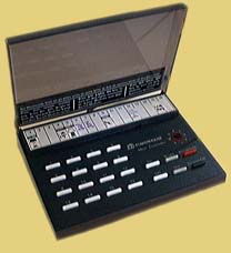
SC503 Maxi Controller
The SC503 is a more recent incarnation of the original series of X10 Command Consoles, such as the CM14311 from the late 1970s. Besides obvious styling and rotary encoder changes, there are a few electrical differences:
- The SC503 features a(presumably more stable)n external transistor-driven 120kHz oscillator, which supplants the internal oscillator on the 78542C IC.
- The SC503 adds bypass disc capacitors to its (undriven) key matrix inputs.
- The LED drive on the SC503 is inverted by a transistor such that the LED is always on unless a button is pushed. The older controllers’ LEDs were normally off, and only lit when a button was pressed.
- Minor component value tweaks.
Otherwise, the SC503 behaves exactly like the older CM14311. One huge advantage of this behavior in terms of testing and aligning X10 modules is that the PLC is generated continuously for as long as any button is held down. On many newer controllers, this facility is only available when there is a bright/dim function present.
The 78542 IC in my SC503 is identical in pinout and operation to the 542C IC in my old CM14311. I found no IC differences whatsoever (outside of numbering and manufacturer), despite at least 14 years of age difference between the two devices.
Modification to make LED light only when a button is pushed
- Unplug SC503 and remove the 4 screws holding the bottom cover in place.
- Unscrew the one screw holding the PCB to the front cover. NOTE: plastic buttons are now loose and may easily fall out of the top cover. Do not flip it over!
- Study the PCB traces and locate the small TO-92 transistor which drives the LED. It may be a BC248 about midway across one edge of the board.
- There should be a 1.8kΩ (or close) resistor connected to one lead. This is the collector (C).
- There should be one transistor lead going directly to IC pin 2, with no other connection. This is the base (B).
- The remaining lead is the emitter and should connect to circuit common (case of either transformer).
- Unsolder and remove the transistor.
- Solder a jumper wire between the former B and C connections.
Done! One aspect of normal operation which may startle anyone not used to the old-style controllers is that a few seconds after A.C. power is removed from the controller the LED will light and stay lit, growing ever dimmer, for roughly 5-10 seconds.
SC503 Alignment
To ensure successful alignment, please be sure to read important information common to all X10 alignment procedures before proceeding.
Frequency Adjustment
- Unplug SC503 and remove the 4 screws holding the bottom cover in place.
- Unscrew the one screw holding the PCB to the front cover. NOTE: plastic buttons are now loose and may easily fall out of the top cover. Do not flip it over!
- Position the PCB in a fashion which allows easy adjustment of the two transformers.
- Connect frequency counter to circuit common (easily found by inspecting PCB) and pins 5&6 of IC (these pins are jumpered together by the PCB of the SC503 to disable the IC’s internal oscillator). Physically, i use the lead of the 10nF capacitor which is closest to the IC.
- Connect SC503, via isolation transformer if needed, to A.C. line. Allow time for counter to stabilize.
- Adjust the coil in the corner furthest away from where the A.C. cord attaches to the PCB for 120kHz.
- Unplug the SC503 and disconnect the frequency counter.
PLC Output Amplitude Adjustment
- Move the SC503 to the location where it will be used. Bring along oscilloscope and powerline signal sensor; connect these to a separate circuit, or at least an electrically distant outlet on the same circuit.
- Set up oscilloscope and powerline signal sensor to monitor the A.C. line.
- Connect SC503 directly to the A.C. line.
- Press and hold any button. House code/particular button do not matter. With no house code selector in place, house code is M.
- Adjust the coil closest to where the A.C. cord attaches to the PCB for maximum 120kHz signal amplitude. This is likely to be a broad, “low-Q” peak.
- Unplug/disconnect all. Reassemble SC503.
Questions/comments may be addressed to: Sonic Purity