Repair Notes for the Breville 800ESXL Espresso Machine
There are many WWW pages which discuss the Breville 800ESXL and/or other espresso machines. This one focuses on failures and repairs, especially electrical. The build quality of the unit in general is very good, and entirely befitting a high-quality appliance in its category. Unfortunately, the electrical circuit board seems to be an exception: the design appears sound… the implementation not so much. Our sample had vastly bad solder joints on every joint on the main PCB, conductive glue, and an overheated resistor (R4) on its way to failure. What originally got me into repairing this out-of-warranty unit was the apparently well-known failure of the pump running spontaneously when the machine was Off. Hopefully something here will be of use to you.
I expect most of you know well what you’re getting into and are well aware of everything mentioned in the following warning, yet since that may not apply to everyone who passes through….
 IMPORTANT: This information is provided AS-IS, for informational purposes only, with no warranty whatsoever. Neither Sonic Purity nor anyone at Siber-Sonic.com can control your ability to successfully and safely utilize this information, and we accept no responsibility for anyone’s actions (beyond our own) related to the content of this website. This equipment utilizes the A.C. power line, which is dangerous. Do not attempt any of these electrical repairs if you have any doubt about your ability to work safely with household powerline-operated devices. It is your responsibility to know and understand common safety procedures, especially those involving electricity at potentially dangerous power levels!
Table Of Contents
Starting in early 2013, new content contributed by site visitors in addition to my own content pushed the size of this former single page to unreasonable heights. Everything is still here, divided into sections. In order, these are:
- Breville 800 Repair Home (this page)
- Normal Sequence of Operations
- Disassembly
- Electrical/Electronic Issues
- Mechanical/Water/Hydraulic Issues
Finding and Interpreting Manufacturing Date Code
Rarely if ever will it be necessary or useful to know your 800’s date of manufacture, though particularly if you’re corresponding with me about an issue, it may help me get a sense of whether yours is an earlier or later production model. The 800 model Breville espresso machine went through an iterative series of refinements and improvements during the course of its production life, which as far as i know are not publicly documented (standard practice).
Most critical are electrical wiring changes, discussed near the start of the Electrical page of this article.
For whatever reason if you or anyone else need(s) or want(s) to know the production date code, at least for the earlier models built in the 2000s, look for a 3 digit number stamped (indented, not printed with ink) into the label on the bottom of the machine, likely around the area pointed to in the photo of the machine here:
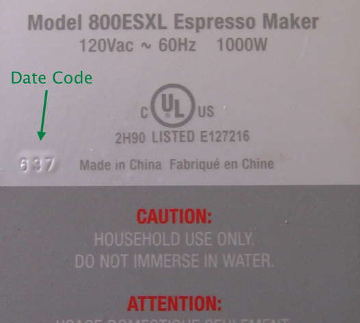
The arrow points to the digits 637. Given that the 800ESXL here was new and received as a gift for Christmas 2006, it makes sense that the 6 in this code represents the last digit of the year—2006. Likely 37 is the 37th. week of the year, which would be 11-17 September in 2006.
I have no idea what the date codes look like for machines manufactured in the 2010s. If anyone reading this has a Breville 800 for which they know the entire ownership history and have reason to believe their 800 was manufactured in 2010 or afterwards, i’d love to receive a message with the information of how that date code works, ideally with a picture i can share here (credited to you or not as you prefer, as usual for all submissions to this article).
Other Sites
No, i am not attempting to compete with Google, Duck Duck Go, nor any other search engine. Site correspondents have occasionally sent along links to what i deem particularly useful or informative information on this series of machines, and/or related models. Some of these URLs below appear elsewhere on other pages of this article; others are only here. Even if they break due to people redoing their sites without proper redirects for the prior design, the broken links may still prove useful in a WWW search, or perhaps on the Internet Archive Wayback Machine (as is the case with several items below).
In no particular order:- extreme breville 800esxl
- Mods & repair tips not covered here. New in February 2022, this site features compelling writing, pictures, videos, and—gasp!—comments! Highly recommended.
- Big Warehouse Spares Repair Diary for 800ES
- Covers all of mechanical/hydraulic/electrical failures. Some repairs are rather obvious, others less so. A good complement to this article, as some of what is covered there is not covered here. (Courtesy Daimon C.)
- Fixing a Breville 800 Series Professional Espresso Machine
- If you have a BES820(XL) or BES830(XL) model with water leakage issues, you may want to start here. Written by Daimon C. and hosted on his site.
- Jim Schulman’s Insanely Long Water FAQ
- Water matters in so many ways beyond taste, for every espresso machine. This article dates back many years, and was originally on the Usenet Newsgroup alt.coffee.
Have any Breville 800ESXL repair tips? Send ’em in! I’ll endeavor to add the seemingly good ones to these pages, at my usual glacial pace. (Please let me know if you want to be credited or remain anonymous. Thanks!)
 World O’ Appliances/Household/Plumbing/Irrigation/HVAC/Hardware